|
|||||||||||||||||||||||||||||||||||||||||||||||||||||||

 |
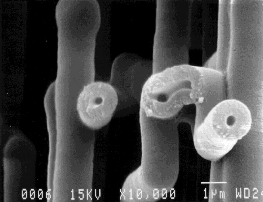 |
| Fig. 4. Scanning electron microscope edge view of a sheet of the oxide tunnels after the surrounding aluminum was dissolved (top), and a closer view of some oxide tunnels (bottom). |
 |
| Fig. 5. Anode tunnel cross-section before (left) and after (right) the oxide formation process. |
 Cathode
The cathode aluminum foil is generally thinner than the anode and must exhibit much higher capacitance than the anode, since the cathode capacitance appears in series with the anode capacitance to yield the total capacitance (See the Appendix). For a given anode capacitance, the maximum total capacitance occurs when the cathode capacitance is as large as possible. High cathode capacitance requires a very low cathode formation voltage. Generally the cathode is not formed at all, but there is always a thin layer (around 2-3 nm) of hydrous oxide on the surface of aluminum unless it is passivated and the electrical double layer also has a large capacitance. A thin hydrous oxide layer forms readily on aluminum with exposure to normal air in the atmosphere. Titanium passivation of cathode foil has been undertaken in recent years to offer a cathode with a capacitance approaching 200 µF/cm2. Such a high cathode capacitance is necessary only for low-voltage capacitors with high-gain anodes. Generally a cathode capacitance of fifty times the anode capacitance is sufficient. This situation yields a total capacitance which is only 2% less than the anode capacitance. For a discharge capacitor, the charge on the anode plate must be neutralized by the opposite charge on the cathode plate, which requires that the cathode be capable of storing a charge greater than or equal to the anode charge. In other words, the product of the capacitance and forming voltage must be larger for the cathode than for the anode. This requirement is generally met automatically, since the charge storage capability of formed foil is maximized at low formation voltage. A thin foil with a surface etch is used for the cathode, giving a frequency response generally better than that of the anode, and giving a large enough capacitance that the total unit capacitance is not diminished. Since the cathode's voltage capability is usually only about one volt, the electrolytic capacitor unit is limited in its steady-state reverse voltage capability to about one volt. It has been found that in some cases transient reverse voltages in excess of 100 volts may appear on the capacitor for durations of around one millisecond with no detrimental effects for thousands of cycles; however it is not clear what the actual cathode potential is in these cases. What is known is that extended reverse voltage for time intervals as short as one second can cause significant heating of the electrolyte and of the anode oxide. The current drawn during these reverse voltages can easily reach hundreds of dc amperes. Electrolytic capacitors can be constructed with formed cathodes to allow voltage reversal without damage. The drawbacks to such construction are reduced total capacitance, since the anode and cathode are in series; and reduced energy density, due to the decreased capacitance and increased mass from the heavier, formed cathode.
Separator
The separator or spacer is an absorbent material in roll form which is wound between the anode and cathode to prevent the foils from coming in contact with one another. The spacer is generally made of paper, which can be of many different types, densities, and thicknesses, depending on the voltage and effective series resistance requirements. Besides separating the anode and cathode, the spacer must wick and hold electrolyte between the plates. The resistance of the spacer-electrolyte combination is appreciably greater than would be accounted for by its geometry and the resistivity of the absorbed electrolyte. The electrolyte-spacer combination also impacts the capacitor's
frequency response.
Electrolyte
The primary purpose of the electrolyte is to serve as a "plate" on the outer anode oxide surface and also to connect to the cathode plate. The electrolyte is a high-resistivity, high-dielectric-constant, high dielectric-strength organic liquid solvent with one or more dissolved, ionically conductive solutes. The secondary purpose of the electrolyte is to repair, heal, or insulate defect sites in the anode aluminum oxide during the application of voltage between the anode and cathode.
Tabs
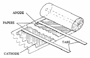
Tabs are strips of aluminum which make contact between the conductive plates and the connection terminals in the header. There may be several tabs connected to each of the plates. Each tab is either cold-welded or staked along the entire width of the anode and cathode foils. The tab paths are generally run from the capacitor section to the terminals in a fashion which keeps the inductance low and prevents tabs of the opposite polarity from coming in contact with one another or the case during movement and vibration of the capacitor unit. The tabs are spot-welded to the underside of the terminals in the header assembly. Tab material is not etched, but is formed to a high voltage prior to its assembly into a capacitor. Optimum tab placement along the foil is considered to be the placement that minimizes power loss due to the metal foil resistance. This optimum leads to equal spacing from each tab to the one nearest it, and half of the inter-tab distance is provided between the outermost tabs and the foil ends. For high voltage capacitors, the tab resistance and metal foil resistance are quite small compared to the oxide and electrolyte resistance.
Package
 |
| Fig. 6. Schematic of the capacitor package. |
 |
| Fig. 7. Some electrolytic capacitors. |
Uses and applications of electrolytic capacitors
 |
| Fig. 8. Monthly global capacitor market. |
Total worldwide usage of capacitors is approximately one trillion units per year. The total market value is approximately 17 billion dollars per year. Figure 8 show the monthly fluctuations of the total capacitor market for a couple of recent years. And Figure 9 presents the annual markets for aluminum and tantalum electrolytic capacitors, which are more than 10% of total usage.
 |
 |
| Fig. 9. Global electrolytic capacitor market: aluminum (left), tantalum (right). | |
Appendix
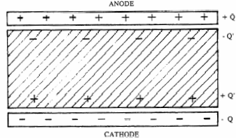
The ratio of the charge magnitude "Q" on each plate to the electric potential or voltage "V" between the plates is known as capacitance "C".
[1] ![]()

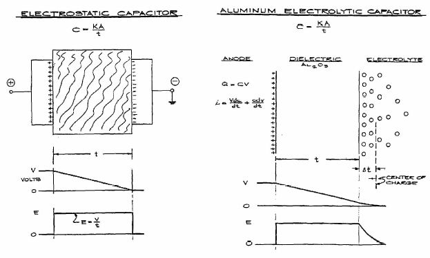
The capacitance of a device depends mostly on the plate geometry and the nature of the dielectric. For two parallel surfaces each having area "A" separated by distance "d" with a dielectric of relative dielectric constant "k":
[2] ![]()

where "Eo" is the dielectric constant of vacuum (8.85×10⁻¹² F/meter). The relative dielectric constant "k" of a material describes its polarizability. As seen in Figure 1, as charges +Q and -Q are established on the anode and cathode plates, respectively, surface charges of +Q' and -Q' on the dielectric are induced according to the following relation which defines "k" for the material: Q' =Q×(1-k).
The cathode capacitance "Cc" is in series with the anode capacitance "Ca" to yield the total capacitance "C" according to the relation:
[3] ![]()

Or, rearranging:
[4] ![]()

Consequently, in series coupled capacitors the lower value capacitor dominates.
![]() Uses and applications of electrolytic capacitor
Uses and applications of electrolytic capacitor
Power supply output filter
When a sinusoidal ac voltage is rectified, a semi-sinusoidal waveform is produced. This waveform is generally converted to a steady dc value by use of a capacitor, which charges to the peak value of the semi-sinusoidal voltage, then provides current to the load at a slightly decreasing voltage until the next half-sine peak restores the maximum voltage to the capacitor. The slight variation in the capacitor voltage is known as the ripple voltage and the current going to and from the capacitor is called the ripple current. To maintain a steady dc output and minimize the ripple voltage, the capacitor's capacitance is selected sufficiently large with respect to the load resistance. A steadier voltage requires a higher value of capacitance and a more costly capacitor. For applications in which the steadiness of the voltage is not very critical, a smaller capacitance is often selected. The ripple current must then be taken into account, for too small a capacitance may have a large effective series resistance (ESR) and may tend to overheat. Maximum ripple current ratings are specified by capacitor manufacturers, and these ratings are derived from the maximum allowable operating temperature of the capacitor as well as the size, mass, construction materials, and ESR of the capacitor. Ripple current ratings in aluminum electrolytic capacitors are available as high as 50 amps rms.
Blocking and dc bypass
The frequency response characteristic of a capacitor is such that it appears to be an open circuit to a steady, dc voltage and a virtual short circuit to high frequencies. As such, the capacitor can be used to route signals according to their frequency content. When a signal containing both dc and ac components is sent to a transformer to amplify the ac portion, often a capacitor is used in series with the transformer to block the dc component, which would cause heating and signal distortion were it to reach the transformer. For such an application the linearity of the frequency response of the capacitor needs to be examined to ensure high fidelity, and the magnitude of the capacitor current needs to be lower than its rated ripple current.
Motor start and other non-polar
The starting torque of ac motors is provided by a motor-start capacitor, often a low-ESR bi-polar aluminum electrolytic capacitor. Such a capacitor is designed for line ac voltage, high current, short-duty operation. Motor-start capacitors have the lowest dissipation factors of the aluminum electrolytics, as low as 2% at 120 Hz. Low-gain foil is used in order to achieve such low ESR. The cases are often made of plastic to provide electrical isolation from the electrolyte potential, which follows the applied voltage. The energy densities are quite low, generally 50 J/kg or less. Even with these low-loss properties, motor-start capacitors quickly heat up in their application, and are only recommended for low duty cycles, such as one second on, one minute off.
Audio applications
Non-polar aluminum electrolytics of 50 and 100-volt ratings are often used in passive crossovers for commercial and consumer loudspeakers, where the signals contain medium ac voltage components (around 30 volts peak) with little or no dc voltage content. Frequency response and vibration resistance of these capacitors are the most important criteria. Electrolytic capacitors have a positive voltage coefficient of capacitance, and this leads to some harmonic distortion.
Car audio (bus stiffening): One ideal application is for large, multi-kilowatt car audio amplifier bus stiffening applications, where the 13 V dc rail may have hundreds of amps peak drawn with every bass drum kick or every bass guitar slap or pop. This can cause the car battery voltage to drop by several volts, dimming the headlights in rhythm to the music and lessening the life of the alternator and battery, not to mention to degrading the audio distortion and output levels. The solution is to use electrolytic capacitors near the amplifiers. These special-purpose capacitors have ratings from 0.5 to 2.0 farads at 15 V dc. These capacitors usually have a series resistance near one milliohm, so are quite effective at stiffening the car's battery voltage, when used at a level of about 1 farad per kilowatt. Future capacitors will probably be rated 0.2-0.5 F at 60 V dc for the higher battery voltages.
Energy discharge applications
The usual energy discharge application for aluminum electrolytic capacitors is in photoflash for photography, both professional and consumer. These capacitors are now also used more and more for laser flashlamp discharges. The military is interested in aluminum electrolytics for low-voltage pulsing of diode-pumped laser radars. For the purposes of this article, aluminum electrolytic discharge capacitors are classified into three voltage regimes: 1. High voltage – greater than or equal to 350 volts rating. 2. Medium voltage – less than 350 volts but greater than or equal to 150 volts rating. 3. Low voltage – less than 150 volts rating.
Photoflash applications
Photoflash capacitors used in built-in consumer camera applications are generally in the range of 100 µF 360 V, and may approach several hundreds of microfarads in the separate camera-top units. These small units are often constructed with two porous anodes side-by-side. Typical energy density is 1.5 J/gram or 2 J/cm3. Professional photographers use banks of electrolytic capacitors in portable but portly units weighing 10 kg or so. These contain many thousand of microfarads, usually in switchable, fan-cooled banks. These are generally screw-terminal capacitors whose construction is very similar to normal, filter capacitors. Photoflash capacitors may be used at an average rate of up to eight flashes per minute, depending on the size, energy, and thermal management. Four flashes per minute is more typical. Photoflash operation often causes an adiabatic internal temperature rise of about 0.05 oC (0.09 oF) per flash. This leads to the conclusion that a few hundred flashes is needed to warm the capacitor appreciably. Therefore, for the first half-hour, one could apply 10 flashes per minute sans souci. Typical flash capacitor life is 50,000 to 200,000 flashes. Long-life designs are available to one million or more flashes.
Strobe applications
Strobe capacitors are used at high repetition rates. In the case of low-voltage units, the repetition rate may be very high, high enough for use in party strobe lights and in automotive tachometer lights. High-voltage units generally cannot be operated in full charge-discharge mode beyond about 2 or 3 Hz repetition rate, or rep rate. High-voltage aluminum electrolytic strobe capacitors use a different alumina dielectric structure than their photoflash and filter counterparts. Strobe capacitors use amorphous alumina rather than the usual crystalline alumina. This is accomplished through the forming process when the foil is anodized. Different pre-processing, process temperature and current density, and different electrolyte chemistry is used. The resulting dielectric is unfortunately much thicker than its crystalline counterpart. For this reason, strobe foil has larger tunnels and strobe capacitors suffer in energy density and cost by a factor of about four against their crystalline cousins. But their repetition rates may offer a factor of twenty improvement, and their life duration may approach 1,000 times the number of sustained charge-discharge cycles. When one only needs a fractional discharge, such as discharging from 400 V to 250 V, instead of full-discharge, hybrid capacitor designs can be developed which offer high repetition rate, long life, without the sacrifices in cost and size required by amorphous foil.
In a normal discharge capacitor application, the capacitor is charged slowly, discharged rapidly, and undergoes a certain number of discharge cycles per unit time. The amount of time required for the capacitor to become charged is referred to as the charge time. The amount of time during which the capacitor is discharged is called the discharge time. A charge-discharge cycle is known as a shot. The number of charge-discharge cycles per second is called the repetition rate, expressed in hertz (Hz). When the repetition rate is very small or the capacitor is not fired often, the operating condition is known as single-shot. When a capacitor undergoes intermittent repetition-rated operation, the duty factor is defined as the time on divided by the sum of the time on and the rest period. The life of a capacitor is defined as the expected number of shots before a specified amount of degradation occurs. Usually the limit is an increase in the ESR.
Related articles
AnodizingElectrochemical capacitors
Further reading
- Application Guide for Aluminum Electrolytic Capacitors.
Reproduced by permission of Cornell Dubilier Electronics, Inc. (an Acrobat pdf file).
- Electrolytic Capacitors, P. McK. Deeley, Cornell-Dubilier, South Plainfield, NJ 1938. An old book available on the WWW by FaradNet.
Bibliography
- Many relevant publications are listed in a website by FaradNet.
Listings of electrochemistry books, review chapters, proceedings volumes, and full text of some historical publications are also available in the Electrochemistry Science and Technology Information Resource (ESTIR). (http://knowledge.electrochem.org/estir/)
Return to: Top – Encyclopedia Home Page – Table of Contents – Author Index – Subject Index – Search – Dictionary – ESTIR Home Page – ECS Home Page
ECS | Redcat Blog | ECS Digital Library