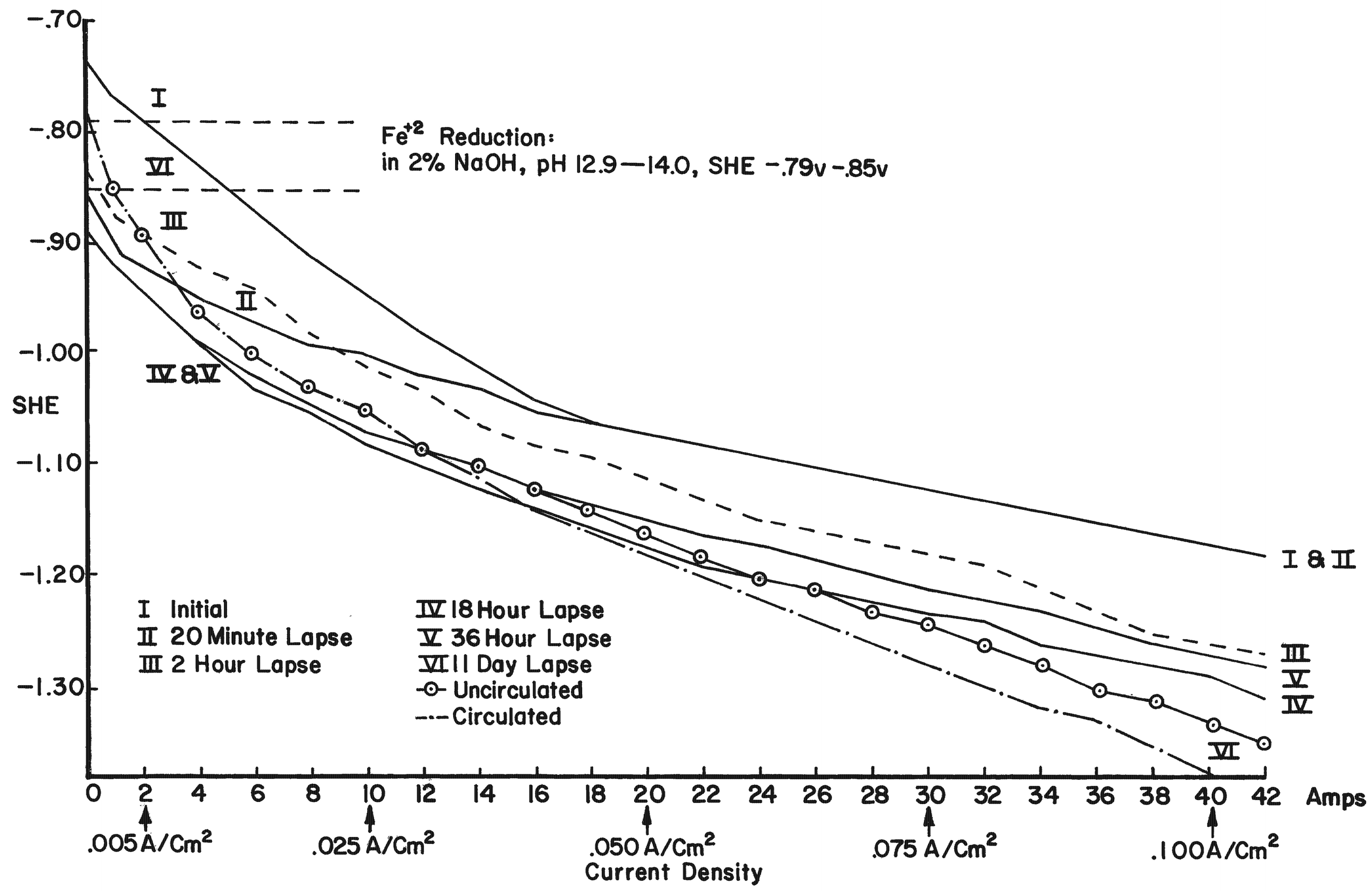
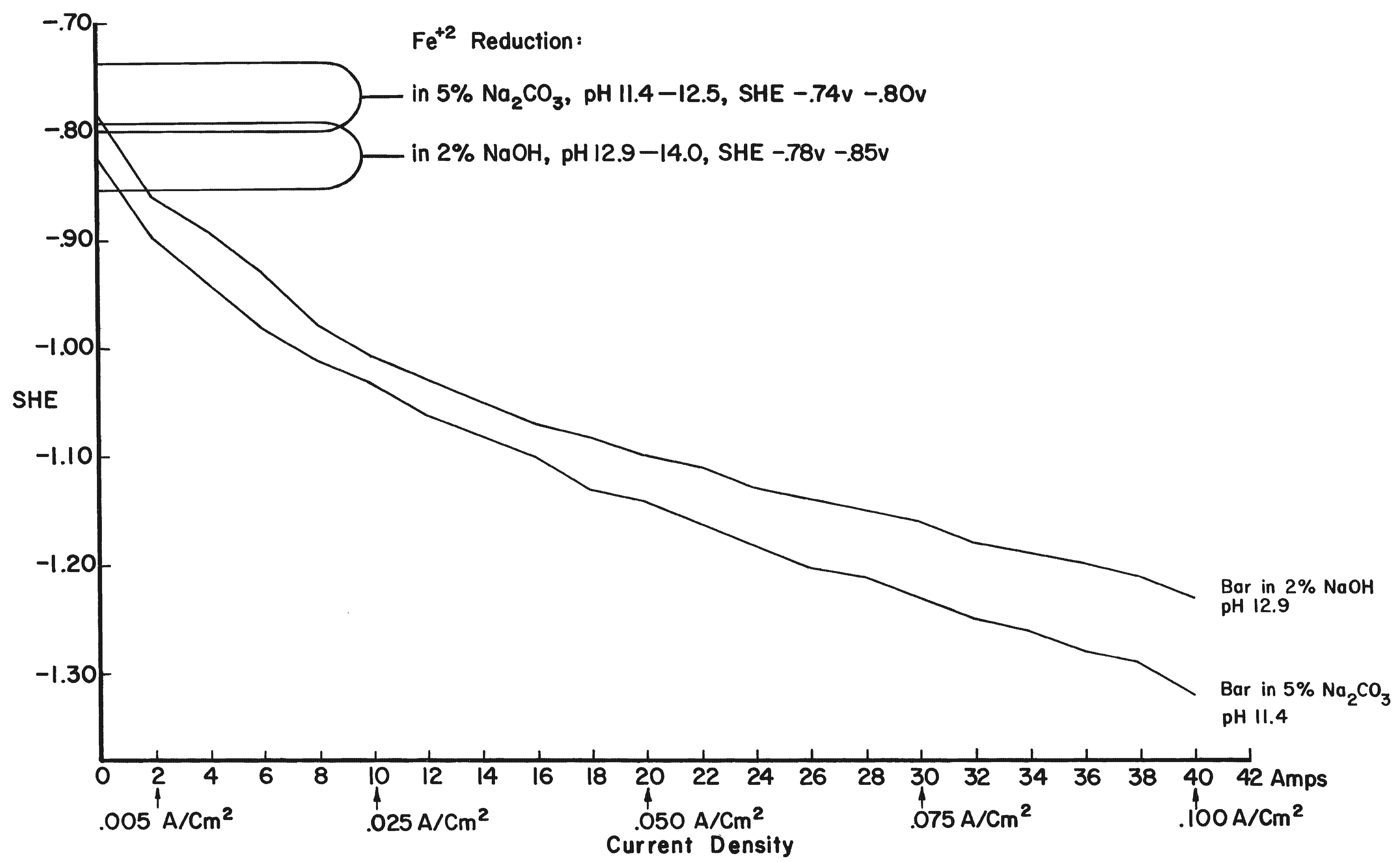
By using electrode potentials it is possible to determine what current density in an electrolyte of known pH is required to establish the condition most conducive to the reduction of ferrous compounds on the metal. (See the Appendix for a more detailed discussion of this subject.) Figure 3 gives the measured potentials of an artifact in an electrolyte of 2% sodium hydroxide with a pH of 12.9 at different current densities over an 11-day period. The initial test was taken before the surface of the artifact was thoroughly saturated with hydrogen, the resistance of the electrolyte had dropped, and the resistance of the artifact was broken down. After a period of 20 minutes, and throughout the 11-day test period, the measurements fell within a rather narrow range. Utilizing the data presented in Figure 8 (in the Appendix), the potential range for ferrous ion reduction at a pH range of 13 to 14 can be determined as -0.79 to -0.85 volts. On Figure 3 this potential range is achieved at a current density below and up to 0.005 amps/cm2, which is barely within the capability range of 2% sodium hydroxide. As can be seen in Figure 4, which compares the potentials of the same artifact in 2% sodium hydroxide and 5% sodium carbonate, the sodium hydroxide is in the more favorable position. The pH of sodium carbonate is not high enough to establish the desired theoretical electrode potentials for the reduction of ferrous compounds. On theoretical grounds a sodium hydroxide electrolyte is clearly superior when reduction of the ferrous corrosion products is the objective. Electrode potentials are affected by temperature, pH value and electrolyte composition. In the conservation of iron it is the pH that is most important. There are several ways of measuring the pH of the electrolyte, but no simple way of determining the pH at the surface of the electrodes. Unfortunately, this is the pH reading of concern. It is known that the pH of the catholyte (the solution at the surface of the cathode where hydrogen is evolved) is higher than the remaining electrolyte. In order to arrive at a reasonable estimation of the prevailing pH at the cathode, the pH of the electrolyte was taken and a maximum increase of one pH for each electrolyte was assumed, for a maximum pH of 14 for sodium hydroxide and 12.5 for sodium carbonate. This approach is imprecise, but no other means was perceived for ascertaining the pH. These adjusted pH ranges are those shown in Figures 3, 4, and 8. Once an electrode potential has been established on the surface of the cathode, periodic measurements and adjustments have to be made in the direct current to maintain that potential. After electrolysis has begun, several hours to a full day are required for the cathode to adjust to an equilibrium state. At the metal surface a metal/hydrogen bond is established and the surface becomes saturated with hydrogen, followed by the evolution of hydrogen. Until the metal surface becomes saturated with hydrogen the potential shifts. Once equilibrium is established the potentials even out. After establishing an electrode potential on an artifact, daily adjustment may be necessary to maintain the potential as the resistance of the electrolyte drops with the addition of dissolved salts and the resistance of the metal and its corrosion products are altered. Before adjusting back to the predetermined potential, one has to be sure that any shift is due to changes in the cathode, and not due to the transport system, that is, the electrolyte through lack of circulation. In Figure 3 the six series of tests were taken over an 11-day period without circulating the electrolyte. On the last day the electrolyte was air-lanced and the test was run again. It can be seen that there are negligible differences in the potential readings in the last two tests except for the potentials at high current densities. The transport system is still adequate, especially at the reduction potentials of ferrous compounds. If any changes occur in the transport system it will become visually apparent at the anode. Even though an alkaline electrolyte is used, acidic areas can form at the anode. In these areas chloride ions react with the positively charged anode to form hypochlorite ions or hypochlorous acid which oxidizes the anode. Adverse reactions are easily detected at the anode by the appearance of a rust stain in at the surface of the electrolyte around the anode, and when this occurs, the cathode is also affected, although it is not as apparent or as detrimental to the operation of the electrolytic cell. The potential at both electrodes is altered, however. Should a change in the potential occur, the electrolyte should be stirred or circulated and the measurements taken again. If the electrode potential remains the same, then the amperage may be adjusted back to re-establish the optimum range. If the problem is not fixed by changing the electrolyte, increasing the pH of the electrolyte, or increasing the electrolyte, the anode will go into complete dissolution within hours filling the vat with a rust slush and coating the cathode. From the standpoint of efficiency, electrode potential measurements are necessary for precise control and quality processing of very select artifacts. The areas of advanced or retarded corrosion will be reflected in the electrode potentials, making it possible for the conservator to identify those areas requiring more extensive reduction and a way to measure the progress of the electrolyte reduction. The data acquired from electrode potential measurements was used to arrive at realistic current densities, that established the approximate electrode potentials for the bulk of the iron artifacts that will require treatment but do not warrant the close supervision or the time required for taking potential measurements. Still, there is the difficulty of arriving at current densities for given artifacts, especially irregular shaped artifacts and differentially corroded artifacts. For these reasons, except for those special artifacts, using either hydrogen evolution voltage or merely visually observing the rate of hydrogen evolution is sufficient.
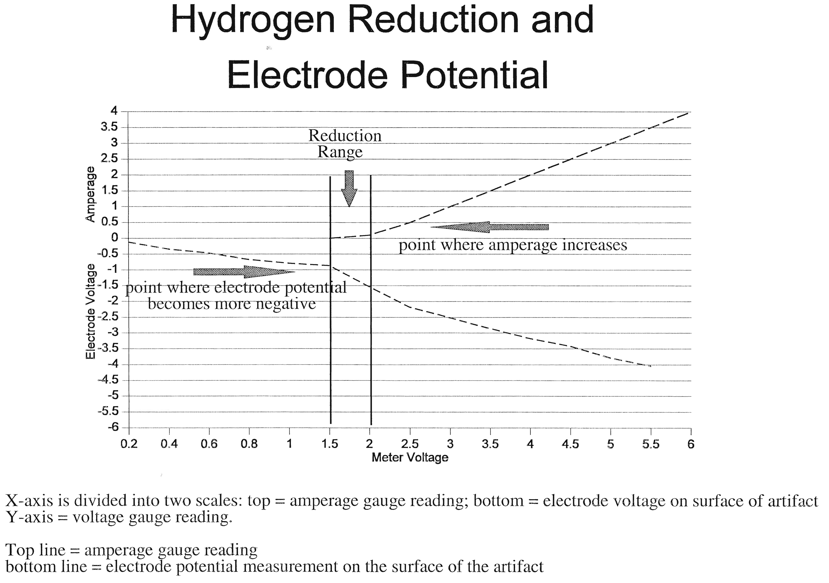
In everyday practice, neither measuring current densities or establishing hydrogen evolution voltage is necessary for most artifact. One can merely "eye ball" the artifact. Start the electrolysis off by slowly increasing the voltage or amperage, until you first began to observe a few bubbles of hydrogen evolving. In theory, for metal reduction you do not need any hydrogen evolution at all, but the irregular evolution of hydrogen from the surface of the metal gives one a visual indicator that the current is flowing. You want the electrons flowing to the cathode to reduce the corrosion products, not produce hydrogen gas. By this technique, neither voltage or amperage is the indicator, it is the evolution of very first evidence of hydrogen evolution. Run the artifact at this setting. However, after a short time, one will observe the evolution of hydrogen increases as the resistance of the artifact is broken down and there is some reduction of the corrosion products in the metal making it more conductive. So, you usually have to decrease the setting back to the point where hydrogen first starts to evolve. After going through this low hydrogen evolution stage, where the objective is to reduce as much of the corrosion products as possible, the current is increase so that there is a steady, but not vigorous, evolution of hydrogen. This is necessary if one wants to remove the maximum amount of chlorides within a reasonable length of time. Maintaining a very low current density current will only prolong the process an unacceptably long time and not contribute any other benefit. As an option, one may choose to run the artifact for a few hours or days at a higher current density that is for maximum mechanical cleaning. In general, I have found that surfaces of the artifacts that might come off at this point during the high current density treatment, have little change of staying intact as you carry it through the rest of the treatments. This process is a simplification over that proposed by North (1987) for it only depends on: (i) visual evolution of slow, irregular evolution of hydrogen for maximum reduction, (ii) visual evidence of a steady evolution, not vigorous, of hydrogen for the much longer process of chloride removal, and optionally, (iii) a vigorous evolution of hydrogen for final mechanical cleaning to remove any last remaining encrustation or loose corrosion products. In practice, this is how most of the experienced conservators determine the current density at which to treat iron artifacts, as well as artifacts of other metals and it works well for most artifacts. (See the Appendix for a more detailed discussion of different aspects of the electrode potential.)
For electrolytic reduction/cleaning of iron, a 16-gauge, one-inch expanded mild-steel mesh is a cheap but efficient open mesh anode material. This steel mesh is readily cut, is relatively flexible, and is easy to "form-fit" as an anode around the artifact. Stainless steel is good and is often recommended, but for large iron objects it is very costly and in most instances is not needed or even as good as mild steel in high chloride electrolytes.
|
||||||||||||||||||||||||||||||||||||||||||||||||||||||||

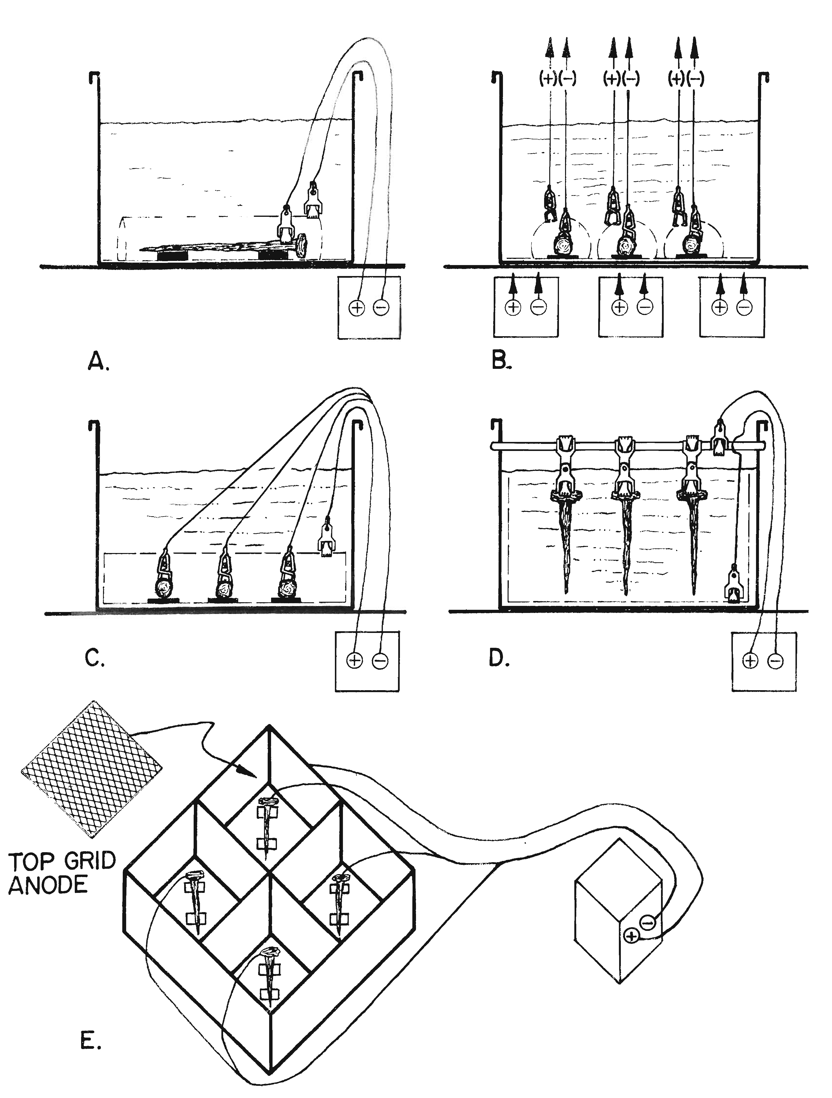 |
| Fig. 6. Electrolytic reduction setups. |
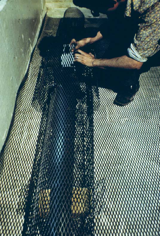 |
| Fig. 7. Form fitting an expanded steel mesh around an iron gun for the �ideal� electrolytic setup. |
The manner in which artifacts are set up for electrolysis (Figure 6) is dependent upon:
- the number of available regulated dc power supplies,
- the current capacities of these units,
- the number and size of the vats obtainable,
- the backlog of artifacts waiting to be processed.
Basically, there are three major ways to set an artifact, the ideal setup, or Type I, Type 2, and Type 3. With the exception of the "ideal setup", each alternative has distinct disadvantages and advantages.
The Type 1 or the �ideal� electrolytic setup (Figures 6-A and 7) consists of a single artifact in one vat, surrounded by a close, form-fitted anode that is equidistant from all surfaces of the artifact and is connected to a single regulated direct current (dc) power supply. With this setup, a conservator is able to precisely regulate the flow of the current to the artifact and maintain a predetermined electrode potential conducive to metal reduction on the surface of the specimen. This setup is used for artifacts that are especially significant and need to be conserved as carefully as possible.
The Type 2 electrolytic setup (Figure 6-B has several artifacts in one vat, but each artifact is surrounded by its own close, form-fitted anode, and each is connected to a separate dc power supply. When this arrangement is used, it is important to make sure that the distance between the different anodes is greater than the distances between the artifact and its anode in order to prevent any cross-over current. (This point is not graphically depicted in Figure 6-B.) With this setup, the current flow to each artifact can be carefully controlled, and the correct electrode potential can be maintained. Since the chlorides present in the electrolyte come from all the artifacts in the vat, it is not possible to determine exactly when a specific artifact is chloride-free. The chloride test does, however, tell the conservator when to change a chloride-contaminated electrolyte and when all of the artifacts are chloride-free.
If an artifact requires close supervision (that is, to consolidate a metal-oxide interface or to preserve some surface or structural detail), it is advisable to hook it up in one of the two methods described above. The most critical variable for precision control is the ability to maintain an even current density on the cathode surface by positioning the anode equidistant from all parts of the artifact while maintaining a steady reduction electrode potential. Monitoring the chlorides during electrolysis is of lesser importance.
The most commonly used Type 3 electrolytic setup where multiple artifacts are connected to a single power supply. Regardless of how it is configured, Type 3 electrolytic setups (Figures 6-C-D) are less desirable from the standpoint of control, but they have the advantage of processing a number of objects at one time in one vat on a single power supply. In one configuration (Figure 6-C), each piece is individually connected to the negative terminal of a single power supply. The artifacts share common anode sheets placed above and below the specimens. An alternative variation of this setup has a common bottom anode and individual top form-fitted anodes to assure a more even distribution of the current to each artifact.
In the most popular Type 3 configuration (Figure 6-D), artifacts are suspended from a brass cathode rod conductor by a double ended Mueller clip. Adjustable vertical anode sheets are hung on either side of the vat, and another anode is laid along the bottom of the vat. This is sometimes referred to as the �sandwich setup�. The oxygen evolved off the bottom anode sheet ensures that the solution is continually mixed, preventing chlorides from concentrating along the bottom of the vat. The increased circulation also helps to maintain the anodes in a passive state by preventing the formation of strongly oxidizing, acidic hypochlorite from forming on them.
The �sandwich setup� with two vertical hanging anodes on either side of artifacts suspended with a clip from a cathode rod has all of the disadvantages discussed above; however, it remains the �work horse setup� when large numbers of artifact need to be conserved. An additional disadvantage is that the proximity of the object to the negative terminal connection is a factor in the current flow. The closer an artifact is to the negative terminal the more current it potentially receives. By regularly repositioning the artifacts, each object will receive an average current for the duration of the treatment. Sandwich setups have the advantage of making it possible to process a number of specimens on a single power supply in one vat. This consideration is important when limited facilities are available to conserve a considerable amount of small artifacts.
It is more desirable (at least for most small objects) to attach artifacts to the cathode rod with double-ended clips. Such clips can be purchased or made by bolting the ends of two clips together. The clips apply a constant pressure and ensure maintenance of a secure contact on the cathode rod and on the artifacts. The clips also facilitate attaching and removing artifacts without unnecessary difficulty.
In all Type 3 electrolytic setups, the conservator is unable to regulate the electrode potential or the current density to each artifact, which lessens the possibility of reducing the appropriate corrosion compounds back to a metallic state. It is also impossible to monitor the chloride loss from any one artifact in Type 3 setups.
There are also a number of setups that involve multiple artifacts, each in an individual cell, but all connected to a single power supply. In Figure 6-E, an example is shown using a mild steel or stainless steel vat with compartments; the vat is connected to the positive terminal and serves as the anode. An artifact can be placed in each of the compartments. When more than one compartment is used, the current to each artifact cannot be controlled, but the chloride level of the electrolyte in each of the compartments can be monitored. This approach takes advantage of limited facilities by using one dc power supply for several artifacts. It also enables the conservator to determine exactly when each object is cleansed of chlorides, keeping the length of treatment of each artifact to a minimum. When an artifact is completed, its compartment can be taken down and set up again without disturbing the electrolytic treatment in other cells. On a simpler level, this setup would be analogous to having two or more metal cans each connected to the same positive terminal of a dc power supply and three separate artifacts hooked to the negative terminal of the same power supply.
A statement should be made here concerning the use of metal vats as the container and the anode. Most dc power supplies used in electrolytic cleaning operate on 6-12 volt range and a 0-50 amperage range, but the actual voltage utilized is usually only 3 to 6 volts. At this voltage there is little personal danger in using metal vats in any of the above setups. Mild steel vats can be constructed in various gauges, but mild steel 55�gallon barrels, cut in half lengthwise, make readily available cheap vats . These containers are surprisingly durable and versatile. Besides being used in electrolysis, they can be employed for rinsing, dehydration, and storage. Even everyday steel cans, such as a coffee can, can be used for small artifacts. In each instance the two terminals must be insulated from each other.
Treatment following electrolytic cleaning
 Final chloride test and rinse
After establishing that the chloride count in the electrolyte has leveled off and ceases to rise when the electrolyte is changed, the artifact is removed from electrolysis, rinsed thoroughly, and placed in a vat of deionized water for a minimum of 24 hours. A sample of the bath water is taken and tested with nitric acid and silver nitrate for the presence of chlorides. The silver nitrate test is suggested because it is simple and is sensitive to minuscule amounts of chloride. If the test is positive, the artifact is returned to electrolysis for further rinsing. If the test is negative, the artifact should be rinsed thoroughly in several changes of alternate boiling and cold water to remove any residual electrolyte and remaining undetectable chlorides. In this rinsing process the boiling water oxidizes the surface of the metal to a flat black color that provides a pleasing appearance.
Once the iron artifact has been thoroughly rinsed in deionized water, it is removed from the last rinse vat while still warm and hot and three coats of tannic acid are applied as described below.
Tannic acid treatment
The corrosion-resistant nature of tannate films on iron was investigated by Knowles and White (1958) and later by Pelikan (1966). In accelerated exposure tests it was found that tannate films on iron were more corrosion-resistant and lasted twice as long as a phosphate-coating. Solutions of hydrolysable tannins such as chestnut, myroblans, or valonea extracts with a pH of 2 to 2.5 provide the most weather-resistant protection (Knowles and White, 1958). If the tannic acid mixture has too high of a pH, phosphoric acid should be added to bring it down to a pH of 2.4. I have found that it is important that the right tannic acid be selected as many are not effective. Tannic acid sold by Baker Chemical has a pH of 2.5 to 3 and has been found to be the most effective (Hamilton, 1976). Tannic acid solutions with a pH of 2.5-3.0 provide good, weather-resistant ferric tannate films. Tannic acid solutions are a standard part of the conservation of all iron artifacts in most conservation laboratories. Although some use the tannic acid coating as the final step, generally speaking, an additional sealant, such as microcrystalline wax, should be applied over the oxidized tannate film for maximum protection.
For maximum protection, at least three coats of 20% tannin solution is applied with a stiff brush. A brushed-on film provides better protection than a dipped or sprayed application because the brushing assures that the solution has access to the metal in areas of loose rust and eliminates the polarization of cathodic areas by the formation of hydrogen (Pelikan, 1966). The tannin solution reacts with the iron or iron oxide to form a ferrous tannate with oxidizes to a mechanically strong, compact blue-black colored ferric tannate. In order to assure a continuous film. Pelikan (1966) found that tannin solutions reacts directly with the metal base and with the rust if the solution is sufficiently acid, pH 2 to 3. In addition to forming a corrosion-resistant film, tannin solutions can be used to impart an aesthetically pleasing black color to iron. Following the treatment of an object with tannic acid a final sealant should be applied to seal off the tannate film.
A sealant, such as microcrystalline wax should be applied over the ferric tannate film formed over the object. The wax will provide a vapor barrier, which the ferric tannate film does not, and will also contribute some strength to corrosion layers on the metal. The wax sealant also mutes the blackness of the tannate film so that is more natural looking. Regardless, of the exact procedure, the application of tannic acid to make the iron more corrosion resistant and gives it a dark black coloration, for many laboratories is considered to be an inherent part of the treatment of any piece of iron, and especially iron recovered from marine environments.
Final sealant
For the past 35 plus years the Conservation Research Laboratory at Texas A&M University has used a synthetic microcrystalline wax which has proven to be very satisfactory. It is relatively simple to use and easy to remove. After the artifact has been thoroughly rinsed, it is placed on top the unmelted wax in a suitable size heated vat. As the wax is heated and melts, the temperature of the metal artifacts slowly rises as the wax is heated to 350oF (176oC). Raising the temperature well above the boiling point of water assures that any remaining moisture in the metal will be vaporized in the molten was. A specimen should be left in the wax until all bubbles stop evolving. The wax is then cooled down to 200-225oF (93�-107oC), the artifact is removed and the excess wax is promptly wiped off with rags. After cooling, if any excess wax remains it can be scraped off or can be removed by heating with a hot air gun or a torch and wiping off the excess wax with a rag. The object is then given a final check and placed in a cool, dry storage facility. A completed specimen should be handled only with clean, dry, gloves, never with bare hands.
General remarks on the cleaning of iron
From our experience over the past 35 years, it is clear that electrolytic reduction is a highly successful conservation technique but that it is a very slow process which cannot be rushed. If the electrolysis is terminated with chlorides still remaining in the artifact (as indicated by either the mercuric nitrate or the silver nitrate test) a fresh outbreak of corrosion will eventually develop. Electrolytic reduction produces attractive, enduring results. It can be accomplished within a reasonable period of time and efficiently removes the soluble chlorides. Even small iron artifacts such as spikes may require 60-90 days. Conservators have often avoided cleaning large objects electrolytically because of their size; however, large objects present no insurmountable problems. Over the past 3 years, the Conservation Research Laboratory conserved large cast iron Civil War cannons from the CSS Alabama and the CSS Westfield. From our experience with large iron objects it is obvious that they will require a minimum of 6 to 24 or more months of electrolysis.Electrolytic cleaning of other metals - concluding remarks
Electrolytic cleaning has been effectively applied to other metals, such as silver, copper, bronze, brass, lead, tin, and pewter. The techniques involved are essentially the same as for either iron or silver. This versatility or electrolytic cleaning makes it one of the conservator's more valuable tools. It can be selected exclusively for its mechanical cleaning action of the evolved hydrogen, for the reduction properties of the process, or, as usually is the case, a combination of the two.
This article has attempted to present the details necessary to duplicate the electrolytic treatment and conservation processes commonly used by conservators. These procedures have proven to be very satisfactory and should give similar results wherever and whenever they are used on artifacts recovered from any archaeological environment be it marine, freshwater or terrestrial. Our most extensive experience has been with iron and silver, and we have found that neither of the materials, nor the sizes of the objects involved, pose impossible problems. We have successfully conserved a number of brass or bronze cannons and thousands of small objects. by variations of the electrolytic reduction/cleaning procedures described here. The conservation of antiquities should produce something that is chemically stable and has an aesthetically acceptable appearance. The treatment should be reversible in case the object should require additional treatment. It should be reversible because after an artifact has been completely processed, unless it is stored or displayed under optimum conditions, it will eventually become chemically unstable from a myriad of possible causes and it will have to undergo additional treatment. The concept of future reprocessing should be taken into consideration in all conservation procedures. The objective of any conservation is to delay this reprocessing as long as possible and to make any necessary retreatment brief.
Appendix
| Table I. Electromotive series of the metals of antiquity | ||
| Metal and its ion(s) | Ionic reaction | Electrode potential (V) |
| Gold (+1 aurous, +3 auric) | Au+3 + 3e- <==> Au | +1.50 |
| Silver (+1) | Ag+ + e- <==> Ag | +0.799 |
| Copper (+1 cuprous) | Cu+ + e- <==> Cu | +0.552 |
| Copper (+2 cupric) | Cu2+ + 2e- <==> Cu | +0.337 |
| Hydrogen (+1) | 2H+ + 2e- <==> H2 | +0.000 |
| Lead (+2 plumbous, +4 plumbic) | Pb2+ + 2e- <==> Pb | -0.126 |
| Tin (+2 stannous, +4 stannic) | Sn2+ + 2e- <==> Sn | -0.136 |
| Iron (+2 ferrous) | Fe2+ + 2e- <==> Fe | -0.440 |
| Iron (+3 ferric) | Fe3+ + 3e- <==> Fe | -0.036 |
| Zinc (+2) | Zn2+ + 2e- <==> Zn | -0.0763 |
The potential series of the metals represent their equilibrium values at a pH of zero. These potentials change with pH value. In order for a metal to be corroded anodically, a potential more positive than the equilibrium value must be established. For cathodic reduction a more negative potential must be created. Cathodic reduction of iron becomes pronounced only if the potential is made considerably more negative than the equilibrium value. Dissolution of the anode becomes significant when the potential is made considerably more positive.
The potentials of the metals are altered if the (ionic) activity (effective concentration) is not normal. Clearly, if the solution is diluted, the passage from the ionic to the metallic state will be slower, whereas the passage from the metal into solution remains unaltered. Thus the balance will be upset, but a fresh balance may be obtained at a more negative potential This means that at 18oC (64oF), if activity and concentration are regarded as identical, every ten-fold dilution will shift the potential in a negative direction by about 0.058 volt for a monovalent ion, or 0.029 volt for a divalent ion. The theoretical shift of potential is approximately realized in the case of the more noble metals; but on some of the less noble metals (iron) the potential actually measured is found to be almost independent of the concentration of the metallic salt in the original solution; this occurs if the metal is capable of reacting with the solution, so that the concentration in the layer next to the metal becomes different from that in the body of the liquid (Evans, 1963).
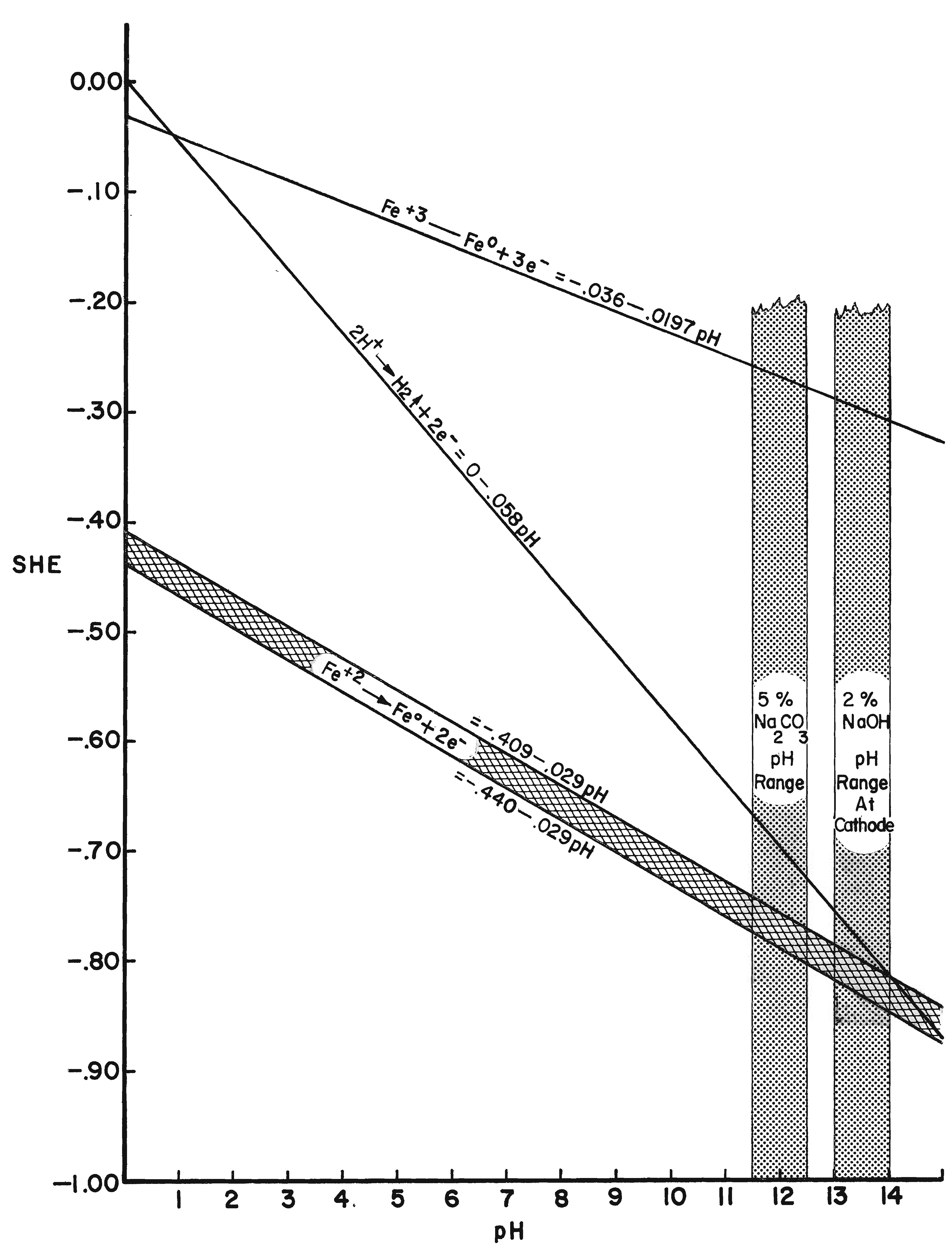 |
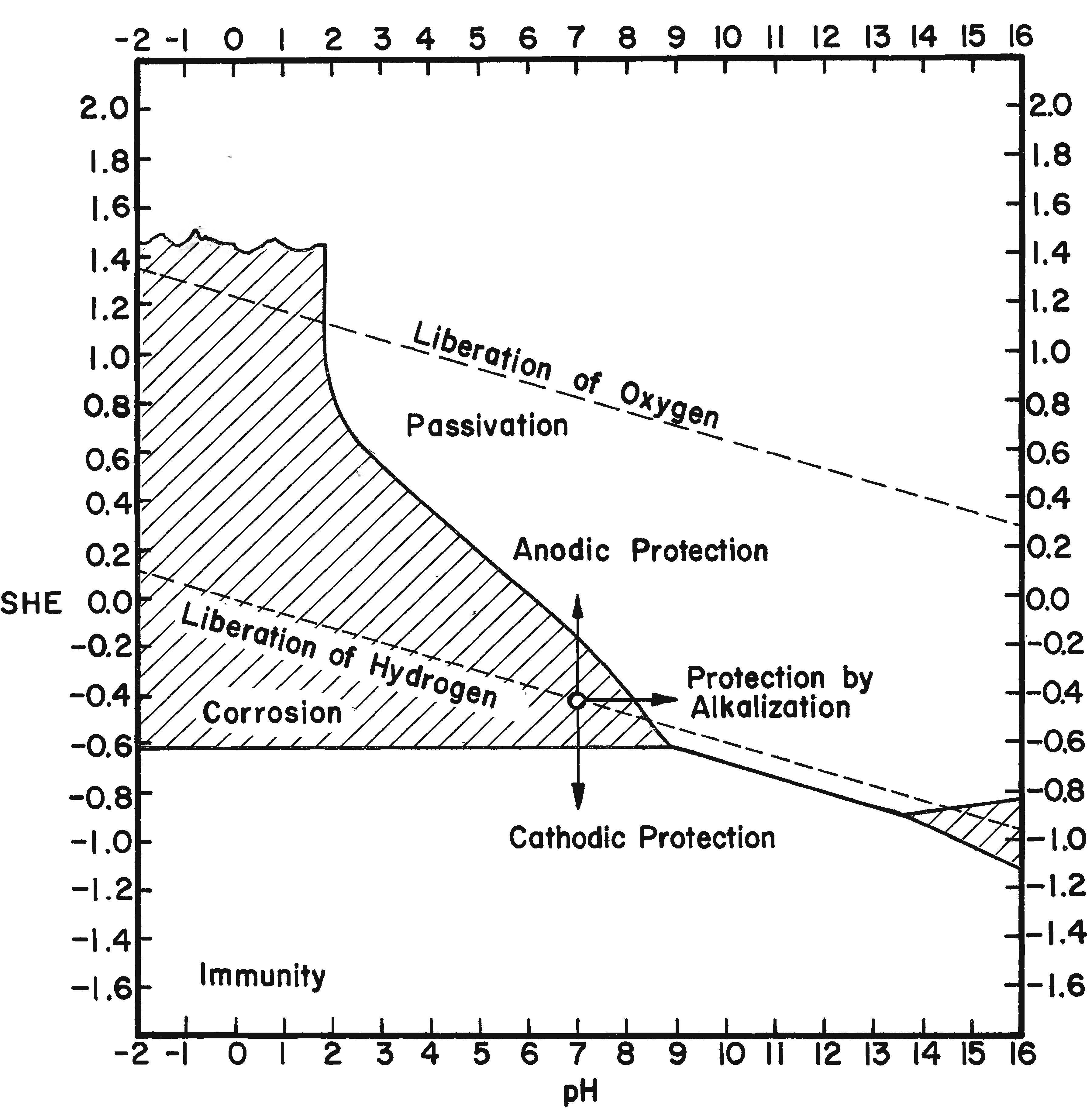
| Fig. 8. Reduction potentials of ferric, ferrous, and hydrogen ions at different pH's and standard temperature of 20oC. The pH ranges of a 5% sodium carbonate and a 2% sodium hydroxide electrolyte are shaded. |
�The potential of iron immersed in an aqueous solution originally free from iron ions depends on the hydrogen-ion concentration, becoming steadily more negative as the pH value rises.�
In electrolytic cleaning of iron the cathode electrode potential is critical because as the hydrogen discharge potential is reached, hydrogen ions are formed, which are utilized to reduce adjacent ferrous compounds. At more negative potentials molecular hydrogen is formed so rapidly that the molecules combine with each other and evolve as hydrogen gas. Any hydrogen evolved as a gas does not reduce oxide compounds. Rather, it acts as a mechanical cleaning agent that physically removes any unconsolidated corrosion layers. The theoretical point for the electrolytic reduction of ferrous ion corrosion compounds is at the intersection of the hydrogen discharge line and the ferrous ion reduction line (Figure 8). Using the formula Fe2+ + 2e- ==> Fe and substituting values for the Fe+2 reduction potential and the correction for pH (-0.440 -0.029 × pH) the intersection appears at a pH of 14.1 and an electrode potential of -0.85. This potential is reached just prior to the evolution of hydrogen. It is possible to establish or at least approach a maximum pH of 14 on the surface of a cathode in dilute aqueous caustic soda. At low current density electrolysis, little or no hydrogen is evident; however, the objective is to establish the electrode potential of the intersection of the discharge potential of hydrogen and the reduction potential of ferrous ions or immediately to the left of this intersection on the cathode surface. It is then theoretically possible to obtain maximum reduction and/or consolidation of the ferrous corrosion compounds.
It has been stated several times that it is energetically impossible to reduce ferric oxide and other ferric iron corrosion compounds in an aqueous solution. This point is graphically depicted in Figure 8. The reduction electrode potential is well out of the range possible for electrolytic reduction in an aqueous alkaline electrolyte and an external emf. By measuring electrode potentials it is possible to insure that a desired electrochemical reaction will occur on a metallic surface in contact with an electrolyte of known pH and ion content. Controlling the electrode potential is the main objective and advantage of electrolytic reduction of metal artifacts. The procedure for measuring electrode potentials is described in Hamilton (1976).
Related article
Corrosion- Methods of Conserving Archaeological Material from Underwater Sites, D. L. Hamilton, 2010.
http://nautarch.tamu.edu/crl/conservationmanual/ - Methods of Conserving Underwater Archaeological Material Culture, D. L. Hamilton, ANTH 605, Conservation of Cultural Resources I. Nautical Archaeology Program, Texas A&M University, 2010.
http://nautarch.tamu.edu/class/ANTH605 - The Archaeologist's Manual for Conservation: A Guide to Non-Toxic Minimal Intervention Artifact Stabilization, B. A. Rodgers, Kluwer Academic - Plenum Publishers, New York, 2004.
- Conservation of Metals, N.A. North, in "Conservation of Marine Archaeological Objects" pp 207-252, C. Pearson (editor), Butterworths, London, 1987.
- The Conservation of Antiquities and Works of Art, H. J. Plenderleith and A. E. A. Werner, Revised Edition, Oxford University Press, London, 1971.
- Basic Methods of Conserving Underwater Archaeological Material Culture, D. L. Hamilton, U.S. Department of Defense, Legacy Resource Management Program, Washington, 1976.
- Conservation of Metal Objects from Underwater Sites: A Study in Method, D. L. Hamilton, Texas Antiquities Committee Publication No. 1, Austin, TX, 1976.
- Conservation of Iron with Tannin, J. B. Pelikan, "Studies in Conservation" Vol. 11, No. 3, pp 109-115, 1966.
- An Introduction to Metallic Corrosion, U. R. Evans, St. Martin's Press, New York, 1963.
- The Protection of Metals with Tannins, E. Knowles and T. White, "Journal of Oil and Colour" Vol. 41, pp 10-23, 1958.
- The Conservation of Antiquities and Works of Art, H. J. Plenderleith, Oxford University Press, London, 1956.
Listings of electrochemistry books, review chapters, proceedings volumes, and full text of some historical publications are also available in the Electrochemistry Science and Technology Information Resource (ESTIR). (http://knowledge.electrochem.org/estir/)
Return to: Top – Encyclopedia Home Page – Table of Contents – Author Index – Subject Index – Search – Dictionary – ESTIR Home Page – ECS Home Page
ECS | Redcat Blog | ECS Digital Library