Return to:
Encyclopedia Home Page –
Table of Contents –
Author Index –
Subject Index –
Search –
Dictionary –
ESTIR Home Page –
ECS Home Page
MICRO FUEL CELLS
Mikayla Smith and Robert F. Savinell
Case Western Reserve University
Cleveland, OH 44106, USA
(January, 2013)
 |
As portable electronic devices advance, with increases in operational speed, improved screen resolution, and higher functionality, there is an increased need for higher energy density and more efficient portable energy sources. Chemical limitations in currently used nickel-metal-hydride and lithium ion batteries prevent their improvement from surpassing 15-25% of the current state-of-the-art, at best. Thus, more advanced energy storage to supplement or to replace batteries is needed. With a much higher energy density than current batteries, micro fuel cells could be one solution. Experts predict that, in the future, fuel cell batteries will be able to last two or three times longer than current batteries (Grinberg and Skundin, 2010). There are differences in the definition of a micro fuel cell, some scientists considering it a very small fuel cell, while others include microfabricated conventional fuel cells within the definition. Independent of the definition, the electrochemical reactions that occur within are common to them all. Applications for portable energy storage devices are almost endless, but the specific requirements of application along with complications related to materials, structures, and manufacturing limitations lead to different design approaches. Despite this technology not yet being available in the marketplace, there is great hope for availability in the future.
Much focus over the past two decades has been placed on fuel cells as a source for future large scale efficient energy conversion, however not as much attention has been given to micro fuel cells. However, good reviews of the work on micro fuel cells can be found in the literature (see the Bibliography). Micro fuel cells have many similarities to conventionally sized fuel cells. The basic components needed for operation of micro fuel cells, such as electrodes, membranes, current collectors, and gas distribution, parallel those needed for conventional fuel cells, but in a miniaturized form. The material composition of the parts may differ however, because of the way the fuel cell is constructed and its processing conditions. Much like traditional fuel cells, micro fuel cells are often not self-contained, since elements such as fuel tanks lie outside of the cell and are connected to it separately. For this reason, some types of micro fuel cells alone are unable to replace batteries in portable electronic devices.
Micro fuel cells are often fabricated using microfabrication processes. Microfabricated fuel cells, on the other hand, are not even necessarily small. �Microfabricated� describes the process by which the fuel cell is made, which are often applied to create microscopic or miniaturized structures and devices. Thus certain flow field components and other structures of a conventional fuel cell might be microfabricated in order to improve performance or to reduce cost. Examples of microfabricated processes include thin-film processes like those used to make silicon chips (Kelley, ... 2002) and thick-film processes like those used to make printed circuit boards (Wainright, ... 2003).
To completely replace batteries, the micro fuel cell must be self-contained and all components including the fuel must be confined within the device. Other challenging design and materials issues include the elimination of pumps or compressors, and a capability to operate on atmospheric air, at ambient temperature and humidity. While various types of micro fuel cells such as those with solid oxide electrolytes are being developed, this article will focus on proton conducting polymer-based hydrogen-air and methanol-air fuel cells.
Fuel cells - how they work
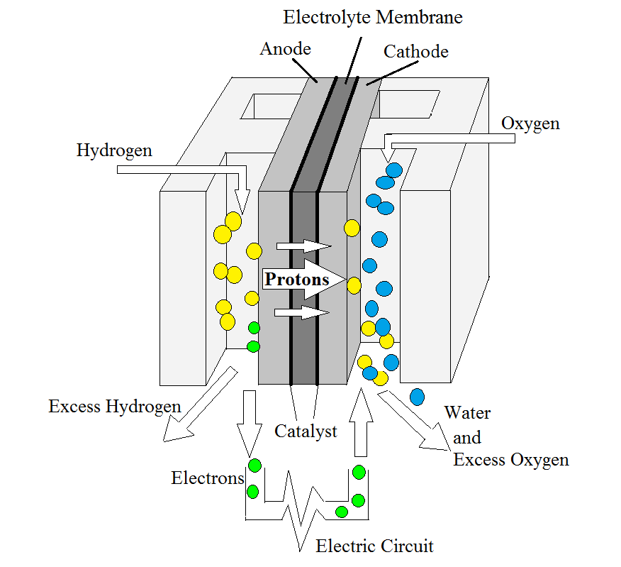 |
| Fig. 1. The reactions occurring within a hydrogen-air fuel cell. |
Fuel cells are electrochemical devices that convert chemical energy from a fuel source into electrical energy by means of oxidation and reduction reactions. In this section we give a brief description of how conventional fuel cells work, and much more detail can be found in available text books and articles shown in the Bibliography. The choice of fuels might be hydrogen or methanol, which is oxidized at the anode, with the oxidant being oxygen from air which is reduced at the cathode. Figure 1 shows the reaction of a hydrogen-air polymer electrolyte fuel cell. Hydrogen oxidizes at the anode platinum catalyst-electrolyte interface causing it to dissociate into hydrogen ions and electrons. Released hydrogen ions are conducted through the electrolyte membrane to the cathode. Reduction then occurs at the cathode platinum catalyst-electrolyte interface (see the Appendix for details).
A proton exchange membrane (PEM) serving as the electrolyte is not electronically conductive, so the electrons that are released from the hydrogen are unable to pass through it, but instead flow through an external circuit from the anode to the cathode. The flow of electrons within the circuit creates an electric current that can be used to power various electronic devices. The reaction will continue until all of the fuel is consumed; thus, the overall reaction equation in a hydrogen-air PEM fuel cell is
the formation of water from hydrogen and oxygen.
Another simple fuel for PEM fuel cells is methanol; and the same basic principles apply. In a direct methanol fuel cell, the oxidation of methanol and the reduction of oxygen result in the production of water and carbon dioxide and the water can be recycled to be used at the reaction occurring at the anode (see the Appendix).
Components of fuel cells
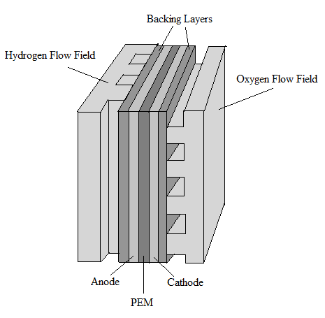
The main structural elements of a conventional
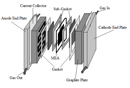
PEM fuel cell include two flow fields, two electrodes, a cathode, an anode, and a proton exchange membrane (PEM). Figures 2 and 3 show the basic structure of a fuel cell. On the outermost ends of the fuel cell are two end plates that are bolted together to hold the fuel cell components together. The end plates are often massive because they hold multiple cells compressed together to boost the overall voltage. An electronically conducting flow field plate is placed against both the anode and the cathode which allows the gases to be fed to the electrodes.
 |
 |
| Fig. 2. The basic structure of a PEM fuel cell. |
Fig. 3. A deconstructed fuel cell. |
Electrolyte
An important component of the fuel cell is the electrolyte separator, as this is the medium through which ions travel from one electrode to the other, balancing the charges that occur because of the reactions. It is also the main structural component that distinguishes one type of fuel cell from another. The electrolyte should have a high ionic conductivity but also be very electronically resistive.
In a
PEM fuel cell the electrolyte is a proton exchange membrane or the PEM. In both methanol and hydrogen fueled cells, the PEM is typically made of perfluorinated sulfonic acid polymer like Dupont�s Nafion. If the PEM is too thin, a high amount of crossover of reactants occurs, but if it too thick, there is a high resistance and therefore a lower voltage output. A Nafion membrane requires hydration in order to conduct hydrogen ions, so operating under ambient conditions is a challenge since too low of hydration will increase cell resistance and too high hydration will cause water to flood the pores in the cathode electrode. Also, swelling of the polymer during fuel cell fabrication or during operation is a special challenge with micro fuel cells.
Electrocatalyst/electrodes
Due to the low operating temperatures of PEM fuel cells, precious metals are required as electrocatalysts. In hydrogen-air fuel cells, platinum nanoparticles are supported on the carbon micron-size particles that make up each electrode, but often the electrodes are at different loadings of catalyst material. In the case of methanol-air fuel cells an alloy of platinum and ruthenium is used as the catalyst for the anode because the ruthenium is able to electro-oxidize the carbon monoxide intermediates that are absorbed onto the platinum surface.
The electrode structures of the catalyst layer are constructed to efficiently transport gaseous or liquid reactants, ionic products, and electrons. For this reason the structures are typically porous with a high surface area, and have electronically and ionically conductive components. The combination of the membrane with the anode and cathode electrode structures is called the membrane electrode assembly (MEA).
Gas diffusion layer
On both sides of the membrane electrode assembly (MEA) is a gas diffusion layer (GDL). The GDL is an electrical conductor used to transport electrons while uniformly distributing gases to the catalyst layer. An ohmic voltage loss often occurring in a PEM fuel cell is due to electrical contact resistances between the GDL and the flow field plate. In hydrogen and methanol fuel cells, typically the GDL is composed of a version of carbon paper that is very porous and has been treated with a hydrophobic polymer.
Ideally, the chemical reaction in the fuel cell should happen fast, efficiently, and effectively and the design and materials of these components of the cell determine these rates and efficiencies.
Design approaches to micro fuel cells
To enable a fuel cell to completely replace a battery, there are many design challenges that must first be overcome in order to make the fuel cell self-contained and portable. To be implemented as a battery, a micro fuel cell must operate at room temperature because it cannot contain heating or cooling devices and the membrane cannot require external humidification. Whether the fuel is hydrogen or methanol, the cell must be able to operate under atmospheric pressure and it must act passively, meaning there cannot be any pumps, fans, or compressors used to move the reactants. Because of the passive nature of the micro fuel cell, those operating on air are often limited in operating current density, perhaps to less than 40 mA/cm2. In addition, the device must be easy and safe to use and reliable. Fabricating the fuel cell device using methods of construction common for microfabricated electronics simplifies manufacturing and reduces cost. An extensive reviews on approaches to micro fuel cell design and materials is summarized in the literature (see the Bibliography).
Among the pioneers in micro fuel cells were Kelley, Deluga, and Smyrl (2000, 2002) who created a miniature PEM fuel cell where all of the components were analogous to that of a large fuel cell, but made through thin-film electronic microfabrication techniques. Their fuel cell was not completely self-contained however, and components such as the methanol fuel were heated. Their research and experimentation still profoundly affected the study of fuel cells, as they found that the performance of a micro fuel cell is able to very closely match that of a large fuel cell operating under similar conditions.
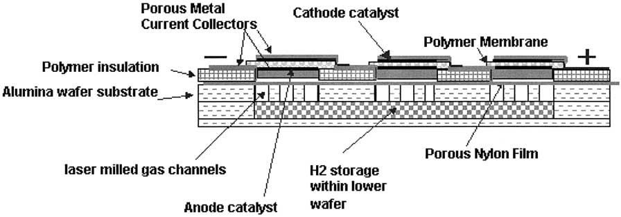 |
| Fig. 4. A cross section of three consecutive hydrogen-air fuel cells. |
Wainright, Savinell, Liu, and Litt (2003) reported a design for a microfabricated polymer based fuel cell with on-board hydrogen storage which can operate passively as Figure 4 shows. The principle of their design lies in a planar array of edge collected cells where the cathodes would be all exposed directly to air and beneath the anodes would be a common fuel cartridge. The electrodes are interconnected through the edge of the individual cells. This is a special ability of the small size electrodes which would lead to high ohmic losses and non-uniform electrode activity for large electrodes. The main components of the cell such as the current collector, gas diffusion layer (GDL), catalyst layers, and electrolyte were manufactured through a process of thick film printing. They report using a Nafion membrane deposition technique that gives a good quality and stable membrane film. On-board fuel storage was a main feature in the design shown in Figure 4. One way of storing hydrogen is to print a metal hydride ink, which has high volumetric hydrogen storage density, into the anode compartment. The anode can then be charged with hydrogen. For this to be a viable on-board storage, the metal hydride has to be charged with hydrogen relatively fast at low to moderate pressures and hydrogen must be delivered to the fuel cell at adequate rates. Another means of storing hydrogen fuel is through a chemical form, for example, such as stabilized sodium borohydride in aqueous solution because it is stable at room temperature for several months when its pH is about 14. When this solution comes into contact with a catalyst, a reaction occurs to separate out the hydrogen which is fed to fuel the cell (see the Appendix). To design the cartridge with the catalyst included, a small well might be etched into the support structure with the catalyst printed at the bottom of the well (see Figure 4). To activate the fuel cell, sodium borohydride solution is injected into the well. Upon solution contact with the catalyst, hydrogen bubbles up to the anode electrode structure. One drawback of this design is the orientation dependency of the cell.
Methanol has been receiving much attention as a potential fuel source for micro fuel cells because it is cheap, easily stored and handled, and in a fuel cell can oxidize at room temperature with an appropriate catalyst. Problems are still posed, however, including its slow reaction and many design challenges that come when one tries to shrink a conventional fuel cell.
One challenge in developing a methanol micro fuel cell is designing a fuel tank that holds enough fuel to run for a reasonable period of time before needing to be refueled. For methanol fueled cells, there is a small range of concentration of the methanol in water within which it will function. A high methanol concentration level seems to be more desirable because the fuel has a higher energy density. However, typically the methanol concentration must be only between 0.5 and 2.0 M because if it is too concentrated, crossover rates (rate at which methanol permeates across the membrane) are too high for the fuel cell to function properly. When a large amount of cross-over occurs, the methanol begins to self-discharge which provides the cell with additional heat instead of electricity while greatly reducing the voltage of the cathode. For this reason, much effort has been put into finding a more efficient membrane that can handle high concentrations of methanol fuel.
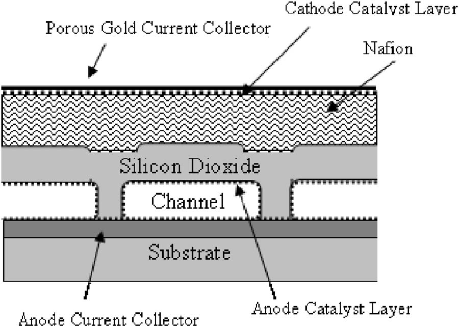 |
| Fig. 5. Design of a cross section of a fuel cell with a composite Nafion and silicon dioxide membrane with fuel microchannels (from Li, ... 2006). |
When designing a fuel cell, the key idea is to increase the cell�s energy and power density while also maintaining reliability. In a portable fuel cell, each and every individual component of the fuel cell must be reduced in size proportionately. This creates issues with the Nafion membrane because when the membrane becomes thin, more fuel crossover occurs. In addition, a Nafion membrane needs to be humidified, which is difficult to maintain without external humidification and operating in a variety of atmospheric conditions. Kohl and coworkers (Moore, ... 2005, Li, ... 2006) proposed a silicon dioxide membrane as a potential solution to this problem because silicon dioxide does not swell with water and is less susceptible to environmental changes or even drying out. The silicon dioxide membrane, however, is a thin glass membrane that is brittle and can be easily cracked or formed defectively. An ideal membrane may be fabricated by layering Nafion on top of silicon dioxide as a composite structure because this helps to ensure long term reliability. They have focused attention on developing such a membrane for a microfabricated fuel cell, and Figure 5 shows their design approach. They have found that by doping silicon dioxide with phosphorus they were able to increase the hydrogen ion conductivity of the membrane. They could therefore make the membrane thicker in order to increase the mechanical strength of the membrane without sacrificing any of the cell�s performance because of the higher membrane resistance.
A look into the future
Even after micro fuel cells are improved enough to be implemented as portable batteries, they still need to be made marketable. Companies must demonstrate that the fuel cell batteries are not too expensive to be replaced or recharged. Some believe that the ideal solution may be to combine lithium ion batteries with micro fuel cells, thus forming a hybrid energy storage system. The hybrid system would have high energy density from methanol fuel and also high power density from the lithium-ion battery. Currently there are three major potential markets for micro fuel cells: portable electronics, portable military equipment and devices, and healthcare segments (Kundu, ... 2007). If researchers are able to develop efficient, reliable, and cost-effective micro direct methanol fuel cells, the method by which small electronic devices are powered could undergo a paradigm change. Current cell phone batteries last about five hours of talk time or two weeks on stand-by; however, Manhattan Scientific Inc. (MSI) expects that a cellphone powered by micro methanol fuel cells would have enough power to last for one week of talk time or six months on stand-by. While micro fuel cells still have a long way to go before their efficiency outweighs there higher cost, when compared to lithium-ion batteries, there are very high hopes for their implementation in the future.
Appendix
Hydrogen-oxygen fuel-cell reactions
| [1] |
H2 ==> 2H+ + 2e- |
(oxidation reaction) |
| [2] |
½O2 + 2H+ + 2e- ==> H2O |
(reduction reaction) |
| [3] |
H2 + ½O2 ==> H2O |
(overall reaction) |
Direct-methanol fuel-cell reactions
| [4] |
CH3OH + H2O ==> CO2 + 6H+ + 6e- |
(oxidation reaction) |
| [5] |
3/2O2 + 6H+ + 6e- ==> 3H2O |
(reduction reaction) |
| [6] |
CH3OH + 3/2O2 ==> CO2+ 2H2O |
(overall reaction) |
Hydrogen storage in sodium borohydride
[7] NaBH4 + 2H2O ==> 4H2 + NaBO2
Acknowledgements
The authors wish to thank Rachel Kapelle of CWRU for her early editorial suggestions and the CWRU SAGES program for support.
Related articles
Fuel cells
PEM fuel cells
Solid-oxide fuel cells
Bibliography
- Progress and Perspectives in Micro Direct Methanol Fuel Cell, S. Sundarrajan, S. Allakhverdiev, and S. Ramakrishna, �International Journal of Hydrogen Energy� Vol. 7, pp 8765-8786, 2012.
- Microfuel Cells: Modern State and Future Development, A Review, V. A. Grinberg and A. M. Skundin, �Russian Journal of Electrochemistry� Vol. 46, pp 963-978, 2010.
- Investigations on Fabrication and Lifetime Performance of Self-Air Breathing Direct Hydrogen Micro Fuel Cells, S. Giddey, S. P. S. Badwal, F. T. Ciacchi, D. Fini, B. A. Sexton, F. Glenn, and P. W.Leech, �International Journal of Hydrogen Energy� Vol. 35, pp 2506-2516, 2010.
- Performance of Micro-PEM Fuel Cells with Different Flow Fields, Y. Lu and R. G. Reddy, �Journal of Power Sources� Vol. 195, pp 503-508, 2010.
- Designing Microfuel Cells for Portable Electronics, B. Flipsen, �Journal of Fuel Cell Science and Technology� Vol. 7, pp 061014-1 - 061014-8, 2010.
- Fuel Cell Engines, M. M. Mench, John Wiley & Sons, Hoboken, NJ, 2008.
- Overview on the Challenges and Developments of Micro-Direct Methanol Fuel Cells (DMFC), S. K. Kamarudin, W. R. W. Daud, S. L. Ho, and U. A. Hasran, �Journal of Power Sources� Vol. 163, pp 743-754, 2007.
- Micro-Fuel Cells � Current Development and Applications, A. Kundu, J. H. Jang, J. H. Gil, C. R. Jung, H. R. Lee, S. H. Kim, B. Ku, and Y. S. Oh, �Journal of Power Sources� Vol. 170, pp 67-78, 2007.
- Microfabricated Fuel Cell with Composite Glass/Nafion Proton Exchange Membrane, J. Li, J. C. W. Moore, D. Bhusari, S. Prakask, and P. A. Kohl, �Journal of The Electrochemical Society� Vol. 153, pp A343-A347, 2006.
- Microfabricated Fuel Cells with Thin-Film Silicon Dioxide Proton Exchange Membranes, C. W. Moore, J. Li, and P. A. Kohl, �Journal of The Electrochemical Society� Vol. 152, pp A1606-A1612, 2005.
- PEM Fuel Cells, F. Barbir, Elsevier-Academic Press, Burlington, MA, 2005.
- Investigation of Acidic Methanol Solution as a Fuel for Microchannel Fuel Cells, J. Li, C. Moore, and P. Kohl, �Journal of Power Sources� Vol. 138, pp 211-216,(2004).
- Microfabricated Fuel Cells, J. S. Wainright, R. F. Savinell, C. C. Liu, and M. Litt, �Electrochimica Acta� Vol. 48, pp 2869-2877, 2003.
- Miniature Fuel Cells Fabricated on Silicon Substrates, S. C. Kelley, G.A. Deluga, and W. H. Smyrl, �Journal of the American Institute of Chemical Engineers� Vol. 48, pp 1071-1081, 2002.
- A Miniature Methanol/Air Polymer Electrolyte Fuel Cell, S. C. Kelley, G. A. Deluga, and W. H. Smyrl, �Electrochemical and Solid-State Letters� Vol. 3, pp 407-409, 2000.
Listings of electrochemistry books, review chapters, proceedings volumes, and full text of some historical publications are also available in the Electrochemistry Science and Technology Information Resource (ESTIR). (http://knowledge.electrochem.org/estir/)
Return to:
Top –
Encyclopedia Home Page –
Table of Contents –
Author Index –
Subject Index –
Search –
Dictionary –
ESTIR Home Page –
ECS Home Page
|