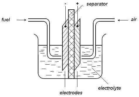
When the two electrodes are connected outside the cell through some electrical device (for example, a lamp), the electrons flow from the anode (the negative pole of the cell) to the cathode (positive pole). Within the cell, the hydrogen ions formed at the anode are transferred (migrate) to the cathode where they participate in the electrode reaction. The moving ions in the solution and electrons in the metal together yield a closed electrical circuit. When the circuit is closed through the external device, the partial reactions proceed and the external electric current is maintained continuously, as long as the reacting gases are supplied to the electrodes. Thus, some of the chemical energy of the overall reaction is converted to electrical energy used in the external device. The remaining part of the chemical energy is lost for practical purposes and it is dissipated as heat, because extra energy is needed to force the reaction to proceed at a finite rate (see overvoltage). However, this loss can be considerable less than the loss occurring in the conventional (thermal-mechanical-electrical) energy conversion systems.
The voltage of a single fuel cell (the potential difference between anode and cathode) is very low � about or even less then one volt. Most user need a higher voltage, for example 6, 12, or 24 volt or more. For this reason, in fuel-cell power plants an appropriate number of single cells are connected in series forming stacks (or batteries, meaning a collection of cells) of fuel cells, that is, the positive pole of a cell is connected to the negative pole of a neighboring cell, and so on, so as to attain the required voltage. A common design is the filter-press design of stacks built of �bipolar electrodes�. One side of such electrodes is working as the anode of one cell and the other side is working as the cathode of the neighboring cell (Figure 3).
|


 |
 |
| Fig. 3. (a) Bipolar electrode; (b) Filter-press fuel-cell stack: (1) bipolar electrode; (2) gaskets; (3) end plate; (4) positive current collector; (5) tie bolts. | Fig. 4. Schematics of a power plant with a fuel-cell stack. |
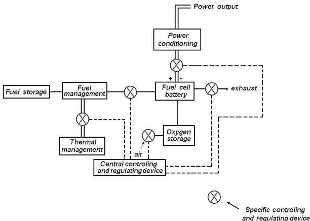
Besides one ore more of such stacks, a fuel-cell-based power plant includes a certain number of auxiliary devices and other components needed to secure a stable uninterrupted working of the stacks (Figure 4). These components include:
- container for the storage of the primary reactants (e.g. natural fuels such as hydrocarbons, coal);
- devices for the management of the primary fuels (purification, reforming, or gasification);
- devices for thermal management (removal of reaction heat excesses or heating of the stack to the temperature needed for the reaction);
- devices for the removal of reaction products;
- valves, pumps, etc. for the reactant supply;
- different regulating and controlling devices;
- power conditioning devices (meters, converters).
There are a number of very important, characteristic, technical parameters describing fuel cells and fuel-cell power plants discussed in the Appendix in some detail.
Low-temperature fuel cells
 The first prototypes
In the 1830s, the British chemists Sir William Grove (1811-1896) conducted a series of experiments on water electrolysis. His device consisted of two platinum electrodes dipping into water acidified with sulfuric acid. After disconnecting the current, the electrodes, at which hydrogen and oxygen had been evolved earlier as gases, were polarized, that is, a certain potential difference was preserved between them. When in this state they were linked by an external circuit, a current was found to flow in this circuit. Grove called his invention a �voltaic battery�. His results were published in 1839 in the Philosophical Magazine. This date is historically regarded as the beginning of fuel cells, although Grove himself did not regard his battery as a practical means for producing electrical energy. (A note by the editor. Similar experiments were also carried out at just about the same time (or even earlier) by Schoenbein.)
In 1889, Mond and Langer conducted relatively successful experiments concerning the generation of electric currents using hydrogen-oxygen cells. At that time, their results were widely discussed in the electrochemical literature. But, as written by Wand in his �Fuel Cell History� (2006): �Much less did anybody know at that time what to do with an invention such as this Fuel Cell. No practical or commercial application was to be found for more than a century. Totally useless in its time.�
Alkaline fuel cells (AFC)
 |
| Fig. 5. Bacon�s stack of hydrogen-oxygen fuel cells, 1960 (From Varta Fachbuchreihe, Band 6). |
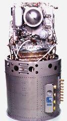 |
| Fig. 6. The 1.5-kW fuel-cell power plant of the Apollo spacecraft (from the UTC website). |
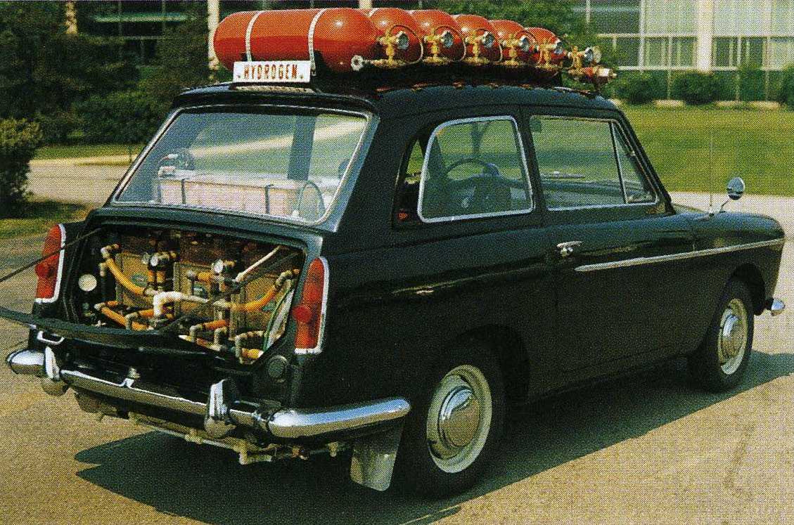 |
| Fig. 7. Early fuel-cell car of Kordesch. |
Phosphoric acid fuel cells (PAFC)
In acidic solutions, the only practical catalyst is platinum (or other metals of the platinum group) for enhancing the electrochemical reactions on both the hydrogen and the oxygen electrodes. In the first prototypes of fuel cells (Grove, Mond and Langer, and others), aqueous sulfuric acid solutions were used as electrolyte. The efficiency of these prototypes was very low. In the following period, many attempts were made to improve this efficiency, but sulfuric acid did not work well as fuel-cell electrolyte. This is due to the fact that the anions of sulfuric acid are readily adsorbed on the surface of the platinum catalysts leading to a considerable reduction of the catalytic activity.
In the early 1960s, concentrated solutions of phosphoric acid were found to give far better results. In contrast with sulfuric acid, the anions of phosphoric acid are not adsorbed on platinum. Furthermore, because the boiling point of concentrated phosphoric acid is high, the working temperature of the fuel cell could be raised to over 200oC (392oF); at these temperatures the rates of the electrochemical reactions are much higher than at the previously used less than 100oC (212oF).
The use of such concentrated (95% and more) phosphoric acid solutions led to the development of highly efficient hydrogen-oxygen (air) fuel cells. In these cells, the liquid acid is contained in the fine pores of a porous matrix with a thickness of about 50 nm. When the matrix is flooded with acid, it behaves like a solid electrolyte, that is, it exhibits an ionic conductivity (for the hydrogen ions), but it is impermeable by the reacting gases. Thus, this matrix acts both as an electrolyte and as a separator preventing the mixing of gases.
The platinum catalyst is deposited in the form of highly disperse (very small) particles on an electron-conducting carbonaceous support. This makes it possible to increase the overall catalyst�s surface area (the reaction zone) without increasing too much the amount of the expensive platinum metal.
During the decade between 1975 and 1985, research in the field of PAFCs was widespread, and many academic and industrial institutions gradually joined the effort. In 1969, UTC Power built a large plant for the mass production of 200-kW PAFC-based power units. These units were operated with natural gas and included equipment for the conversion of natural gas to hydrogen and for hydrogen purification. They were designed for combined, on-site, heat and power supplies of residential and municipal structures, such as hospitals, etc. In 1983, UTC Power developed and built in Japan, together with Japanese companies, a 4.8-MW power plant. This PAFC plant used large electrodes, measuring 0.34 m2. This plant operated between 1983 and 1985, and it produced a total of 5400 MWh electrical energy.
After 1995, very few papers appeared on phosphoric acid fuel cells in the scientific literature. Of course, many of the different power plants built in earlier periods still function, but work on their further development and improvement has practically ceased. Despite the short period during which PAFC fuel cells received prime attention, they played an important role in the development of fuel cells. For the first time, the large-scale industrial production of fuel-cell power plants has begun. Many scientific and business circles world-wide have recognized that fuel cells have a real potential for applications useful to humankind.
Proton-exchange-membrane fuel cells (PEMFC)
Towards the end of the 1950s, Thomas Grubb and Leonard Niedrach at General Electric developed the PEM fuel cell, a hydrogen-oxygen fuel cell using a proton-conducting solid ion-exchange membrane as electrolyte. This fuel-cell version was commercialized, and in the early 1960s it was used for power generation in the Gemini spacecraft. This was a historical event, the first practical application of a fuel cell as a power supply. The success of this application promoted the further development of different kinds of fuel cells. When the Gemini flights ended, work on this type of fuel cell almost ended, and for subsequent space flights NASA relied on the more efficient alkaline fuel cells (see above). Work on �proton-exchange-membrane fuel cells� (also called �polymer-electrolyte-membrane fuel cells�) was not taken up again until the very late 1980s.
 |
| Fig. 8. Schematics of a single PEMFC: (1) bipolar plates; (2) current collectors; (3) gas-diffusion layers; (4) catalytic layers; (5) membrane. |
The core of a PEMFC (and also of some other types of fuel cells) is the membrane-electrode assembly (MEA) consisting of an ion-exchange membrane sandwiched between the two (hydrogen and oxygen) electrodes. Each electrode in turn consists of a catalytic layer containing the dispersed platinum catalyst deposited on carbonaceous supports (mostly carbon black and graphitized cloths) and of a thin, porous gas-diffusion layer that enables a uniform supply of the reacting gas to the catalyst�s surface sites.
The structure of a single PEMFC cell is shown schematically in Figure 8. Each cell is separated from the neighboring cells by an electronically conducting bipolar plate. The plate is in contact on one side with the positive electrode of a given cell and on the other side with the negative electrode of the neighboring cell. The plates contain channels on both sides, supplying the reacting gases to the multilayered MEA placed between two bipolar plates.
In PEMFC stacks, the required number of cells are clamped as a block between two end plates, which also serve as the terminals for drawing the current. In addition to the individual cells with their bipolar plates, special heat-exchange plates are included in the fuel-cell stack for removal of the heat evolved during operation.
The working temperature of PEMFCs is about 80oC (176oF). The operational voltage of a single cell varies, depending on the current drawn, between 0.6 and 0.85 V.
 |
| Fig. 9. Bus with electric fuel-cell power plant (from the UTC website). |
Direct-methanol fuel cells (DMFC)
Hydrogen is a very active reducing agent (fuel). Thus, in hydrogen-oxygen fuel cells very high operating currents and high values of the specific power per unit weight can be achieved. However, the handling, storage, and transportation of the hydrogen fuel are very complicated. This is a problem primarily for relatively small power plants of the portable type. For such plants liquid fuels are more realistic.
Methanol is a highly promising fuel for small, portable fuel cells. It is considerably more convenient and less dangerous than gaseous hydrogen. In contrast with petroleum products and other organic types of fuels, methanol has a rather high activity for electrochemical oxidation (although not as high as hydrogen). Its specific content of chemical energy of about 6 kWh/kg, although lower than that of gasoline (10 kWh/kg), is quite satisfactory. For this reason, its use in fuel cells for power plants in electric vehicles and different portable devices is widely discussed today. The electrochemical reactions taking place in the direct-methanol fuel cell are shown in the Appendix.
Beginning in the early 1960s, the mechanism of this reaction was the subject of many studies in different countries. At the same time, numerous attempts were made to build test models of methanol-oxygen (air) fuel cells. Due to the relatively low rate of methanol oxidation on platinum, considerable amounts of platinum catalyst had to be used in these models. Still, the specific power attained was quite small. For this reason, interest gradually subsided and for a long time it was assumed that, for practical applications, methanol can be used as fuel in fuel cells only after its preliminary conversion into hydrogen.
Only in the mid 1990s, after the great successes achieved in the development of hydrogen-oxygen fuel cells with the proton-conducting ion-exchange membrane, was a breakthrough reached in the development of fuel cells with direct (without preliminary conversion) oxidation of methanol. Fuel cells of this type were now called �direct-methanol fuel cells� (DMFC). The design of modern DMFCs is very similar to the design of proton-exchange-membrane fuel cells. The same membranes (Nafion®) and similar catalysts are used in both fuel cells. The main difference between them is the nature of the fuel. Methanol can be supplied in two ways: in gaseous state after preliminary evaporation, or in liquid state as an aqueous methanol solution. The latter leads to a much simpler cell design because no special evaporator is needed. It has also the advantage that a sufficient amount of water is supplied with the fuel for maintaining a high ionic conductivity of the membrane.
There is a basic problem with the operation of DMFCs that does not exist with the proton-exchange-membrane fuel cells. In the latter, the membrane is practically impermeable by the reactants (hydrogen and oxygen) and thus prevents their intermixing. In contrast, in DMFC the membrane is partially permeable by methanol dissolved in the aqueous solution. For this reason, some of the methanol penetrates from the anode part of the cell through the membrane into the cathode part. This phenomenon is called �methanol crossover�. This methanol is directly oxidized on the platinum catalyst by gaseous oxygen without producing useful electrons. This has two consequences: (i) a substantial part of methanol is lost for the electrochemical reaction, and (ii) the potential of the oxygen electrode is shifted to lower positive values and therefore the operating voltage of the fuel cells is diminished. Despite many investigations up to now it was not possible to solve completely this problem.
A potential area of application for DMFCs is low-power (up to 20 W) power sources for electronic equipment, such as notebooks, video cameras, DVD-players, cell phones, medical devices, etc. At this time, the application of DMFCs as power sources for electric vehicles is very remote. Despite the large amount of research performed, DMFCs, in contrast with proton-exchange-membrane fuel cells, are still not in commercial production or in wide practical use.
High-temperature fuel cells
Aqueous solutions are used as electrolytes in all the fuel cell types described above. Furthermore, in fuel cells with ion-exchange membranes, a certain amount of liquid water is needed in order to maintain a sufficient ionic conductivity of the membrane. Consequently, the working temperature of these fuel cells is limited to temperatures well below the boiling point of water. There are other types of fuel cells with a working at temperatures above 300oC (572oF) using nonaqueous electrolytes and membranes that do not need water for conductivity. These high-temperature fuel cells have a number of advantages.- It is not necessary to use expensive platinum-metal catalysts. The rate of electrochemical reactions increases with temperature, and their rate on catalytically less active metals (for example, nickel) is quite satisfactory for practical purposes.
- It is not necessary to use highly purified reactants. In the low-temperature fuel cells, even small amounts of certain impurities (such as carbon monoxide in hydrogen) will deactivate the platinum catalyst by adsorbing on the surface, leading to a substantial lowering of the operating efficiency. At higher temperatures, this phenomenon is practically not observed.
- It is possible to use fuels other than hydrogen. One of the main advantages of high-temperature fuel cells is the possibility to use carbon monoxide as a fuel. Carbon monoxide is readily obtained by steam gasification of coal as �water gas�, a mixture of carbon monoxide and hydrogen. This opens the possibility for an indirect electrochemical utilization of huge coal reserves.
- It is possible to directly integrate the reforming of natural fuels with the fuel cell. Despite the higher temperatures, the rates of direct electrochemical oxidation of natural fuels, such as petroleum products or natural gas (methane), are still negligibly small. For this reason, natural fuels can be used only after conversion to hydrogen. The catalytic conversion (reforming) of natural fuels requires a considerable amount of heat. Thus, it is reasonable to directly couple the reforming with the fuel cell. In this case, the heat evolving at high temperatures during the operation of the high-temperature fuel cell can be used for the reforming reaction, thus increasing the overall efficiency of the fuel utilization. Such combined units containing high-temperature fuel cells and reforming are often called internal-reforming fuel cells (IRFC).
Molten-carbonate fuel cells (MCFC)
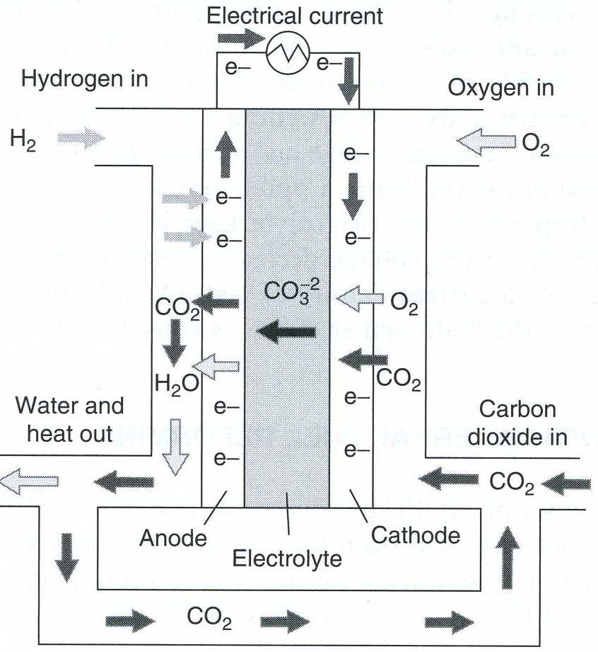 |
| Fig. 10. Schematics of reactant flow in a MCFC (From Wikipedia, the free encyclopedia.) |
In the carbonate melt, metal and carbonate ions are formed and provide the conductivity of the electrolyte. As in these melts there is no water or hydrogen ion present, the electrochemical reactions are quite different from those occurring in low-temperate fuel cells (see the Appendix for details). In MCFCs, the reactions include the carbonate ions and carbon dioxide. It is a special feature of MCFCs that, unlike most other versions of fuel cells, the cathodic reaction consumes not only oxygen but also carbon dioxide, while at the same time carbon dioxide is produced in the anodic reaction. Therefore, it is necessary to return the carbon dioxide, evolved at the anode, to the cathode during the operation of a MCFC (Figure 10).
In about the mid-1960s, industrial organizations in many countries (USA, Germany, Japan, and others) became interested in MCFCs, and began the development and production of power plants based on these cells. By 2000, more than 40 power plants, ranging in size from 250 kW to 1 MW, were built and installed. The largest MCFC power plant, with a power of 2 MW, was built in 1994/1995 in Santa Clara, California. Due to some technological troubles, the operation of this plant was terminated in 1996. This plant operated for about 6000 hours and produced 2500 MWh of electrical energy.
Solid-oxide fuel cells (SOFC)
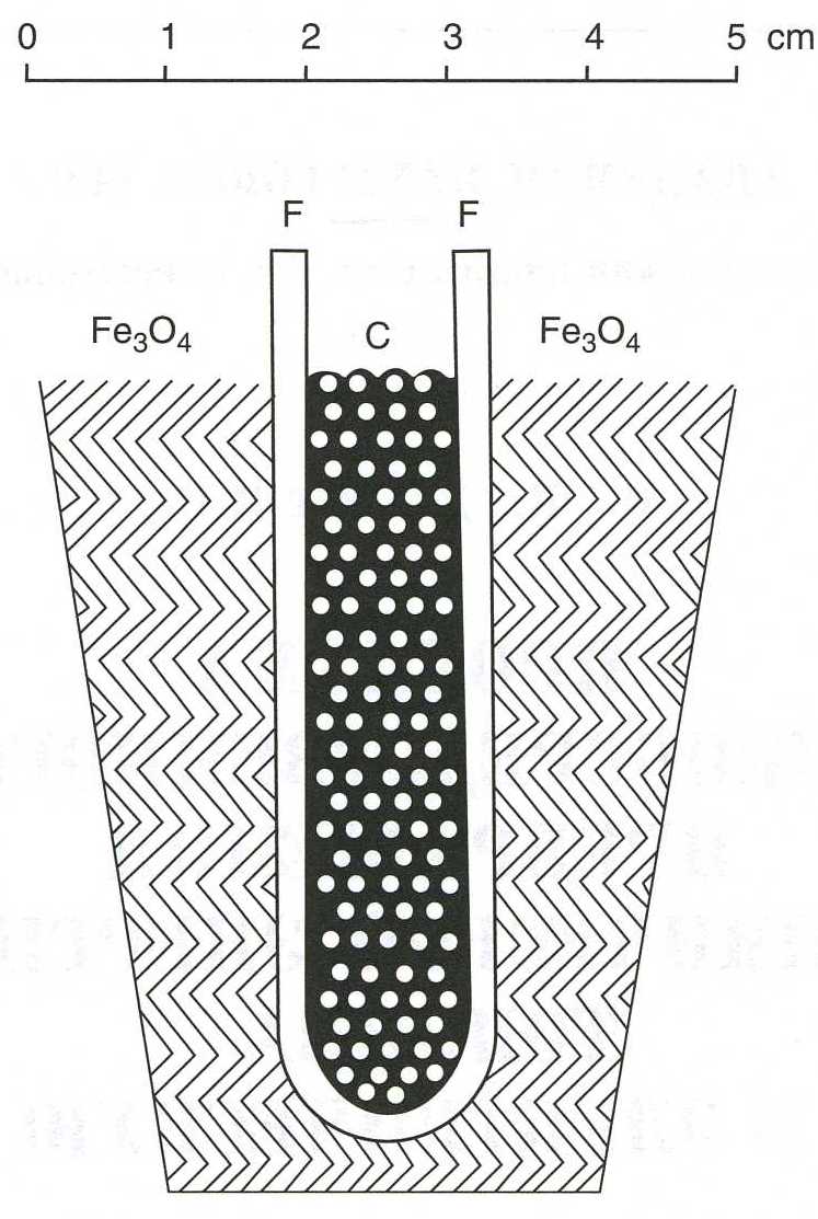 |
| Fig. 11. Coal battery of Baur and Tobler (1933) |
Already in the 1930s, the Swiss scientist Emil Baur, who worked also on molten-carbonate fuel cells, tried to use this Nernst mass for a fuel cell with carbon as fuel working at a temperature of 1000oC (1832oF) (Figure 11). The lifetime of this �carbon cell� was very short. In order to increase lifetime and conductivity of such solid electrolytes, the Armenian scientist Oganes Davtyan, who worked in Moscow, performed in the 1940s numerous studies with mixtures of different oxides of rare-earth elements.
At the start of the new period of fuel cell development, Weissbart and Ruka, of the Westinghouse Electric Corporation, developed a fuel cell with an YSZ type electrolyte of tubular shape in 1962. From this time on, such a tubular design was widely adopted for SOFCs. In 1968, Westinghouse, together with the German company Siemens, formed a joint enterprise, Siemens-Westinghouse, specializing in the further development and commercialization of tubular SOFCs. This enterprise soon became the world leader in this field.
In modern tubular S-W cells, ceramic tubes are produced by extrusion of the cathode material (lanthanum manganite with the addition of some alkaline-earth metal oxides). On the outside of the tubes, a thin layer of the YSZ electrolyte is applied by vapor deposition of the electrolyte�s ingredients. On top of the electrolyte, an anode material (nickel and nickel-oxide powder) is applied from of a slurry. The working temperature of such tubular SOFCs is about 900oC (1652oF). As the conducting ions in the electrolyte are oxygen ions, the electrochemical reactions in a hydrogen-oxygen SOFC are different from those in the low-temperature or molten-carbonate fuel cells (see the Appendix for details).
A new orientation of work in the field of fuel cells
Success in the development of proton-exchange-membrane fuel cells led to the emergence of a new direction of work in the field of fuel cells. Apart from work toward building powerful plants for more efficient grid-power generation, a second application, that of building autonomous power sources of intermediate or small capacity, is also pursued. Such power sources are intended for applications were grid energy is inaccessible, such as transportation, portable devices, and remote areas. The term �fuel cell� began to lose its original meaning as electrochemical power source operated by natural fuel, and acquired the meaning of an electrochemical power source that, in contrast with ordinary batteries, work continuously as long the reactants are supplied. The first application of this type was in the Apollo and Gemini spacecrafts. At present, large-scale work in these areas is under way in many countries. Large fuel-cell plants for grid power
 |
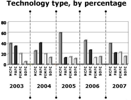 |
| Fig. 12. Annual number of large, stationary fuel-cell units and MW installed (from Adamson, Fuel Cell Today, 2007). | Fig. 13. Technology type of large fuel-cell units, by percentage (from Adamson, Fuel Cell Today, 2007). |
It has been already mentioned that, using proton-exchange-membrane fuel cells, the UTC-Power company produced a large number of stationary (200-kW) power plants for decentralized energy and heat supply for residential and community buildings. Large, multi-megawatt power plants, using different types of fuel cells, were built in many countries. Figure 12 shows the number of such plants constructed every year between 1996 and 2007, as well as the electric power added every year (in megawatts per year). Figure 13 shows the percentage of the various fuel-cell systems used year by year to build these plants.
 |
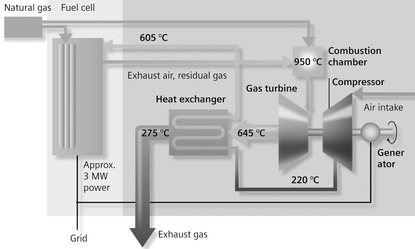 |
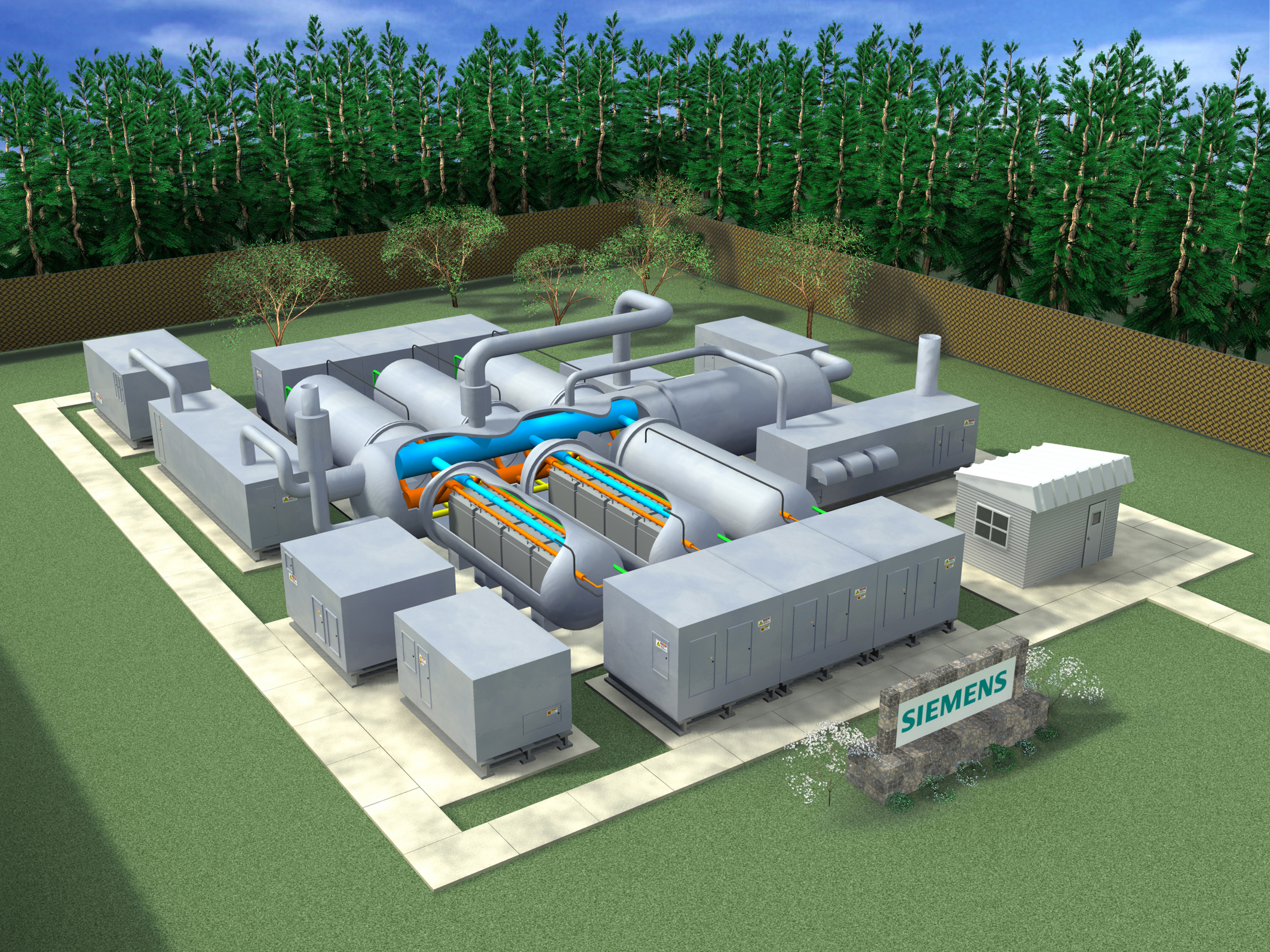
| Fig. 14. Overall view of a 3-MW SOFC-based Siemens-Westinghouse power station. | Fig. 15. Schematics the hybrid power plant shown on Figure 15. |
During recent years, efforts have been under way to build hybrid plants, combining high-temperature fuel cells and gas turbines. The basic idea of such hybrid plants is the highly efficient coordination of the gas and heat flows entering and leaving the two components of such combined power plants. Such an arrangement would diminish energy losses and would increase the overall efficiency. Figure 14 shows the overall view, and Figure 15 a schematics, of a 3-MW solid-oxide fuel-cell based Siemens-Westinghouse hybrid power plant scheduled to go on-stream in 1912. It is expected to achieve an overall efficiency of 70%, thanks to the combustion of residual hydrogen in a gas turbine as well as to other improvements.
Small fuel-cell plants for portable devices
In the past, different types of storage batteries or disposable batteries were used as power sources for portable electric and electronic devices, such as flashlights and portable radio receivers. In the 1990s, the mass production of many new types of electronic devices for domestic, medical, and military use began (notebook computers, video cameras, cellular phones, video players, individual communication equipment, etc.). Portable devices need very low power for their operation, not more than 5-10 W and often even in the milliwatt range. However, batteries can sustain uninterrupted functioning of these devices for only a few hours. The necessity to replace or recharge the batteries after their discharge and exhaustion is a grave shortcoming of these new devices. The need for new power sources with longer uninterrupted working time became very acute. This led to the beginning of a large amount of research and development work for the development of small-size, low-power fuel-cell plants (so called mini-fuel cells). The introduction of these mini-fuel cells to domestic applications could open ways for a broad commercialization of fuel cells.
Fuel-cell plants for electric vehicles
The increasing vehicle traffic in large cities is causing of considerable air pollution with greenhouse gases (carbon dioxide) and with many toxic substances, such as carbon monoxide, nitrogen oxides, and sulfur containing compounds. The health problems resulting from this air pollution has caused a number of countries (and notably the state of California in the USA) to make it mandatory for carmakers to produce and sell a certain number of low-, even �zero-emission� vehicles. The carmakers were thus forced to find ways to replace internal-combustion engines by other power units. One of the possibilities is to develop electric cars. Electric cars powered by batteries are in relatively large use for transportation within production plants and for certain home deliveries, such as milk products and mail. Battery-powered cars have a very limited driving range, less than 80-100 miles, between battery charging stops. After exhaustion of the batteries, they need a long time to be recharged (�refueled�). These defects prevent the possibility of the large-scale introduction of battery-powered cars as replacement of internal-combustion vehicles. The use of medium-size fuel-cell plants (50-100 kW) as power sources for electric cars would solve both problems of driving range and refueling time. For this reason, almost all large carmakers are now beginning to explore the possibility of producing efficient and convenient fuel-cell vehicles. It soon became evident that this task involves some basic problems. One of these problems is the difficulty to store the heavy and bulky tanks with compressed gaseous hydrogen on small vehicles. For this reason, it is probable that internal-combustion engines will be replaced by fuel-cell plants first of all in large vehicles (trucks and buses) that are responsible for a large part of air pollution in large cities. Two other problems (the cost of fuel-cell plants and their lifetime) will be discussed in the next section.
The main problems in the field of fuel cells
As described above, all main fuel-cell systems have already left the experimental research and development stage and became an economic reality. Many large-scale power plants based on these systems have been built. They have already demonstrated lower consumption of natural fuels per unit of power generated and lower emission of greenhouse gases and other harmful products. These developments were in a great part the results of work initiated and/or financed by government programs. At present, work on development of medium-sized power plants based on proton-exchange-membrane and direct-methanol fuel cells for electric vehicles is also partially sponsored by different government programs.In contrast, government bodies were not involved in the development of small-size fuel-cell power plants for portable devices based mainly on proton-exchange-membrane and direct-methanol fuel cells. Development in this field has been mainly market-driven (apart from the closed military sector). For this reason, the commercial production and uses in civil applications of such plants are still progressing slowly.
There are two problems to be solved to secure a broader use of fuel-cell power plants in the potential multimillion-dollar markets of electric vehicles and new types of portable electronic devices.
Economic problems
At present, the manufacturing cost of fuel-cell power plants is very high in comparison with other types of power plants. This is not only due to high labor costs (which can be significantly reduced with increased production volume) but also to high cost of materials. One of the most important components of all proton-exchange-membrane and direct-methanol fuel cells (the Nafion® membrane) is very expensive, about 700 $/m2. Despite a drastic decrease of the amount of platinum used on the electrodes of these fuel cells, the price of the platinum catalysts is still considerable. According to a paper of Kamarudin (2006), the total cost of a 5-kW proton-exchange-membrane fuel-cell power plant will be about 1200 $/kW; with 500 $/kW for the actual fuel cell stack (membrane: 55 $/kW, platinum: 52 $/kW) and 700 $/kW for the ancillary equipment (pumps, heat exchangers, etc.). In comparison, the cost of an analogous internal-combustion engine is 500-1500 $/kW.
A further reduction of the manufacturing costs is a prerequisite for a possible future mass production and commercialization of fuel-cell-powered electric cars.
The problem of lifetime
For any practical application of fuel-cell plants, they must show a satisfactory lifetime during which a smooth operation in a given mode is possible. For small plants used in portable devices, the lifetime must be about three years. For electric vehicles, it must be about five years, and for large stationary multi-megawatt power plants, it must be up to ten years. Samples of single proton-exchange-membrane fuel cells and fuel-cell stacks have been successfully operated for several thousands of hours. These results can be regarded as very promising since they show that fundamentally a proton-exchange-membrane fuel cell can be operated for several years. However, there is not enough data available for general use of this type of fuel cells. For this reason, large-scale research efforts are under way at present concentrated on finding the reasons for the gradual decline of the efficiency and for the premature failure of individual fuel cells.
Appendix
Hydrogen-oxygen fuel-cell reactions in acidic electrolyte
| [1] | H2 + ½O2 ==> H2O | (overall reaction) |
| [2] | H2 ==> 2H+ + 2e- | (oxidation reaction) |
| [3] | ½O2 + 2H+ + 2e- ==> H2O | (reduction reaction) |
![]() Direct-methanol fuel-cell reactions
Direct-methanol fuel-cell reactions
| [4] | CH3OH + 3/2O2 ==> CO2+ 2H2O | (overall reaction) |
| [5] | CH3OH + H2O ==> CO2 + 6H+ + 6e- | (oxidation reaction) |
| [6] | 3/2O2 + 6H+ + 6e- ==> 3H2O | (reduction reaction) |
![]() Molten-carbonate fuel-cell reactions
Molten-carbonate fuel-cell reactions
![]() Using hydrogen as fuel:
Using hydrogen as fuel:
| [7] | H2 + ½O2 ==> H2O | (overall reaction) |
| [8] | H2 + CO32- ==> H2O + CO2 + 2e- | (oxidation reaction) |
| [9] | ½O2 + CO2 + 2e- ==> CO32- | (reduction reaction) |
Using carbon monoxide as fuel:
| [10] | CO + ½O2 ==> CO2 | (overall reaction) |
| [11] | CO + CO32- ==> 2CO2 + 2e- | (oxidation reaction) |
| [12] | ½O2 + CO2 + 2e- ==> CO32- | (reduction reaction) |
![]() Solid-oxide fuel-cell reactions
Solid-oxide fuel-cell reactions
| [13] | H2 + ½O2 ==> H2O | (overall reaction) |
| [14] | H2 + O2- ==> H2O + 2e- | (oxidation reaction) |
| [15] | ½O2 + 2e- ==> O2- | (reduction reaction) |
Very important parameters of fuel cells are their open-circuit voltage �Uo� and their operating voltage �Ui� as observed under given conditions (at a given operating current). The voltage of a working cell will be lower the higher the current �I�. Sometimes this relation is expressed by a simplified equation:
![]() Technical parameters of fuel cells
Technical parameters of fuel cells
[16] ![]() Ui = Uo + IRapp
Ui = Uo + IRapp
where the apparent internal resistance �Rapp� is conditionally regarded as a constant.
The operating current of a fuel cell at any given voltage �Ui� across an external load with the resistance �Rext� is given by Ohm�s law:
[17] ![]() I = Ui / Rext
I = Ui / Rext
Since �Ui� in turn depends on the current, by combining the last two equations the expression for the current becomes:
[18] ![]() I = Uo / (Rapp + Rext)
I = Uo / (Rapp + Rext)
During operation of a fuel cell, the power delivered is �P = Ui × I�, or using the above equations:
[19] ![]() P = Ui2 Rapp / (Rapp + Rext)2
P = Ui2 Rapp / (Rapp + Rext)2
Neither the current nor the power output are sole characteristics of fuel cell since both are determined by the external resistance (load) selected by the user.
For sustainable thermal conditions in an operating fuel cell, it will be often necessary for the operating current not to fall below a certain minimal value �Imin� or to rise above a certain maximal value �Imax�. The range of admissible values of the operating current (of the power output) and the ability to work with different loads are important characteristics of each fuel cell.
The overall mass of fuel-cell power plants �Mtotal� include two components: (i) the mass of the power plant proper �MPP� with all auxiliary devices but without the reactants and their containers, and (ii) the mass of the reactants (fuel and oxygen) and the corresponding containers �Mreact�. The last mass depends on the expected operation time �τ�, and for a constant load (operating current) it is proportional to this time �Mreact = mreact × τ�. Where �mreact� is the mass of the reactants needed for one hour of operation. Thus the overall mass is a linear function of the operating time:
[20] ![]() Mtotal = MPP + mreact × τ
Mtotal = MPP + mreact × τ
Often a need arises to compare electrical and other characteristics of fuel cells differing in their size or nature. This is most readily achieved when using reduced or normalized parameters, for example, specific power referred to unit of power plant�s mass �MPP� (W/kg) or specific energy referred to the power plants overall mass �Mtotal� (Wh/kg) or the analogous specific parameters referred to unit of corresponding volumes.
Theoretically a fuel cell should work indefinitely as long reactants are supplied and reaction products and heat are removed. In practice however the efficiency of a fuel cell declines in the long run. This is seen from a gradual decrease of the cell voltage (usually rated in units of µV/h).
Related articles
Current density distribution in electrochemical cellsFlow batteries
Micro fuel cells
Nonrechargeable batteries
PEM fuel cells
Solid-oxide fuel cells
Bibliography
- Fuel Cells: Problems and Solutions, V. S. Bagotsky, Wiley, Hoboken, NJ, 2009.
- Advances in Fuel Cells Vol.1, S. Zhao, K.-D. Kreuer, and T. V. Nguyen (editors), Elsevier, New York, 2007.
- Fuel Cells: From Fundamentals to Applications, S. Srinivasan, Springer, New York, 2006.
- Technical Design and Economic Evaluation of PEM Fuel Cell Systems, S. K. Kamarudin, W. R. W. Daud, A. Md.Som, M. S. Takriff, and A. W. Mohammad, �Journal of Power Sources� Vol. 157, pp 641-649, 2006.
- Fuel Cell History Part 1, G. Wand, �Fuel Cell Today� June 16, 2006.
- Handbook of Fuel Cells: Fundamentals, Technology, Applications (four volumes), W. Vielstich, A. Lamm, and H. Gasteiger (editors), Wiley, Chichester, UK, 2003.
- High Temperature Solid Oxide Fuel Cells: Fundamentals, Design and Applications, S. C. Singhal and K. Kendall (editors), Elsevier, New York, 2003.
- Fuel Cell Systems Explained (2nd edition), J. Larminie and A. Dicks, Wiley, New York, 2003.
- A Historical Perspective of Fuel Cell Technology in the 20th Century, M.L. Perry and T. F. Fuller, �Journal of the Electrochemical Society� Vol. 149, pp S59-S67, 2002.
- Quantum Jumps in the PEMFC Science and Technology from the 1960s to the Year 2000, P. Costamagna and S. Srinivasan, �Journal of Power Sources� Vol.102, pp 242-269, 2001.
- Intermittent Use of an Alkaline Fuel Cell-Hybrid System for Electric Vehicles, K. Kordesch, J. Gsellman, M. Cifrain, S. Voss, V. Hacker, R. R. Aronson, C. Fabjan, T. Hejze, and J Daniel-Ivad, �Journal of Power Sources� Vol.80, pp 190-197, 1999.
- Polymer Electrolyte Fuel Cells, S. Gottesfeld and T. A. Zawodzinski, in �Advances in Electrochemical Science and Engineering� Vol. 5, pp 195-301, R. C. Alkire, H. Gerischer, D. M. Kolb, and C. W. Tobias (editors),Wiley-VCH, Weinheim, Germany, 1997.
- Fuel Cells and Their Application, K. Kordesch and G. Simader, VCH, Weinheim, Germany, 1996.
- 25 Years of Fuel Cell Development (1951-1976), K. Kordesch, �Journal of the Electrochemical Society� Vol. 125, pp 78C-91C, 1978.
- Hydrogen-Air/Lead Battery Hybrid System for Vehicle Propulsion, K. V. Kordesch, �Journal of the Electrochemical Society� Vol. 118, pp 812-817, 1971.
- Kalte Verbrennung: Fuel Cells = Cold Combustion, E. W. Justi and A. W. Winsel, Steiner, Wiesbaden, Germany, 1962.
- A Solid Electrolyte Fuel Cell, J. Weisbart and R. Ruka, �Journal of the Electrochemical Society� Vol. 109, pp 723-726, 1962.
- High-Temperature Fuel Cells, G. H. J. Broers and J. A. A. Katelaar, in �Fuel Cells� Vol. 1, pp 78-93, G. J. Young (editor), Reinhold, New York, 1960.
- The High Pressure Hydrogen-Oxygen Fuel Cell, F. T. Bacon, �Industrial and Engineering Chemistry� Vol. 52, pp 301-303, 1960.
- Batteries with Solid Ion Exchange Membrane Electrolyte, W. T. Grubb and L. W. Niedrach, �Journal of the Electrochemical Society� Vol. 107, pp 131-135, 1960.
- The Problem of Direct Conversion of the Chemical Energy of Fuels into Electrical Energy (in Russian), O. K. Davtyan, Academy of Sciences, Moscow, 1947.
- Fuel Batteries (in German), E. Baur and J. Tobler, �Zeitschrift fur Elektrochemie� Vol. 39, pp 169-180, 1933.
- Electrochemical science, its present and technical future (in German),W. Ostwald, �Zeitschrift fur Elektrochemie� Vol 1, pp 122-125, 1894.
Available on the WWW.
- A New Form of Gas Battery, L. Mond and C. Langer, �Proceedings of the Royal Society of London� Vol. 46, pp 296-304, 1889.
Available on the WWW.
- �On a Gaseous Voltaic Battery, W. Grove, �The London and Edinburgh Philosophical Magazine and Journal of Science� Ser. 3, Vol. 21, pp 417-420, 1842.
Available on the WWW.
- On the Polarized Condition of Platina Electrodes, and the Theory of Secondary Piles, W. Grove, �The London and Edinburgh Philosophical Magazine and Journal of Science� Ser. 3, Vol. 14, pp 446-449, 1839.
Available on the WWW.
- On Voltaic Series and the Combination of Gases by Platinum, W. Grove, �The London and Edinburgh Philosophical Magazine and Journal of Science� Ser. 3, Vol. 14, pp 127-130, 1839.
Available on the WWW.
- On the Voltaic Polarization of Certain Solid and Fluid Substances, C. F. Schoenbein, �The London and Edinburgh Philosophical Magazine and Journal of Science� Ser. 3, Vol. 14, pp 43-45, 1839.
Available on the WWW.
Listings of electrochemistry books, review chapters, proceedings volumes, and full text of some historical publications are also available in the Electrochemistry Science and Technology Information Resource (ESTIR). (http://knowledge.electrochem.org/estir/)
Return to: Top – Encyclopedia Home Page – Table of Contents – Author Index – Subject Index – Search – Dictionary – ESTIR Home Page – ECS Home Page
ECS | Redcat Blog | ECS Digital Library