There are three main reasons for using hydrogen. First, among all fuels (methanol, ethanol, formic acid, etc.), the weight-based energy density of hydrogen fuel is the largest at 33.3 Wh/g. Second, of all the flowing fuels (fluidized solids, liquids, vapors, gases) you could use, hydrogen is the easiest to oxidize under near ambient conditions of temperature and pressure. The third reason is that if the cathode uses air, specifically oxygen in air, then the process in the fuel cell can be zero emission (greenhouse gas and pollution free) because the only products are electricity, heat, and water. PEM fuel cells are only zero emission if there is no (or a net zero) consumption of hydrocarbons anywhere in the process.
Solid polymer electrolytes possessing acid-based functional groups have numerous advantages, making PEM fuel cells attractive for smaller scale applications such as portable power, backup or stationary (combined heat and power), and finally transportation. Some of the PEM fuel cell�s attractive features are: continuous operation (no recharging), a compact system, high power density, and relatively low temperature operation (under 90oC or 194oF), as well as low/zero emission from the fuel cell system when operating on hydrogen.
| ||||||||||||||||||||||||||||||||||||||||||||||||||||||||||||||||||||

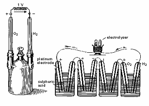 |
| Fig. 2. 1842 drawing of first apparatus demonstrating the concept of fuel cell. |
The precursor to the modern day acid electrolyte fuel cell was innovated in 1889 by L. Mond and C. Langer. Oxygen and hydrogen were also used as the oxidant and fuel, respectively, while platinum or gold foils were used as the electrodes, platinum black (high surface area, fine powder platinum) as the electrocatalyst, asbestos as the separator or membrane, and finally an electrolyte immersed in porous materials like earthenware. This early fuel cell could also be combined into stacks, and was the basis for today�s phosphoric acid fuel cells (PAFC) and PEM fuel cells.
Although Grove invented the fuel cell, it was Friedrich Wilhelm Ostwald, one of the founders of physical chemistry, who provided much of the theoretical understanding for how fuel cells operate. Grove knew optimization of the three phase interface would improve performance, but the theoretical knowledge did not yet exist to explain why. The interconnected roles of the fuel cell�s various components (anions, cations, oxidizing and reducing agents, electrolyte, and electrodes) and hence the fundamental knowledge regarding the three phase interface was determined experimentally by Ostwald in 1893. In 1894 he proposed that single step electrochemical energy conversion of hydrocarbon fuels (coal) in a fuel cell is more efficient than thermochemical energy conversion of the same fuel. However, only theoretical energy conversion was considered and not the more practical aspects such as feasibility and efficiency of coal electrooxidation. Nonetheless, the foundation for all future fuel cell research was laid by Ostwald�s experiments on the underlying chemistry of fuel cells.
The next leap in PEM fuel cell research was from the 1950�s to the 1970�s at General Electric (GE), where PEM fuel cells were developed for, and used in, NASA�s Gemini Space Program. Working at GE, Grubb and Niedrach used sulfonated polystyrene as the membrane electrolyte in the 1950�s.
Then, in the 1960�s high power and energy densities were achieved, and Dupont�s Nafion was introduced as the membrane electrolyte in 1966. There was no waste in the system, and the water produced could be used for drinking purposes by the astronauts. Nafion is a proton conducting solid polymer electrolyte made out of perfluorosulphonated polymers.
 |
| Fig. 3. Plot of power against calendar year for each generation of developed Ballard PEM fuel cell stack. |
During the 1990�s Ballard Power System�s researchers achieved over an order of magnitude increase in power density over the previous state of PEM fuel cell technology as shown in Figure 3. The significant power density increase allowed commercial automotive applications to be considered for the first time. This was accomplished through a combination of advanced design and materials, using carbon powder supported platinum particles as the catalyst, making the best mixture (catalyst ink) of this catalyst, electrolyte (conductive ionomer), the right amount of waterproofing agent, and then coating this catalyst ink either on the gas diffusion layer or on the proton conductive membrane to fabricate the catalyst layer and the corresponding MEA. Such advances allowed Ballard to obtain this considerable achievement earning them international recognition.
PEM fuel cell technology
 Single cell, stack, and system
Single cell
As a single cell consists of only one anode and cathode, its maximum theoretical voltage (based on the lower heating value, or LHV) is 1.23 V at room temperature and ambient pressure. The operating voltage will be less, and at normal current densities such as 1 A/cm2, a typical cell voltage is 0.6 V. An example of a NRC-IFCI in house designed fabricated built and operated single cell is shown in Figure 4.
 |
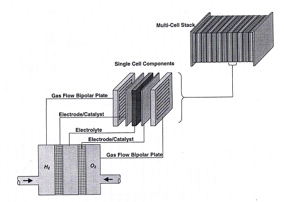 |
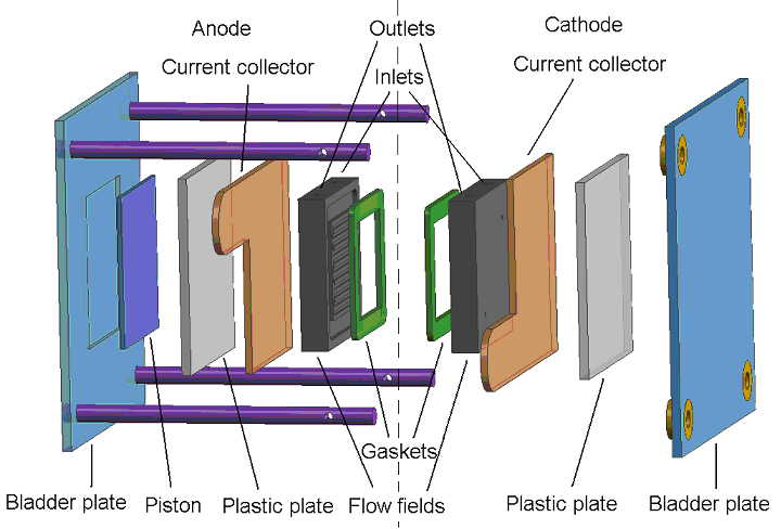
| Fig. 4. Exploded view of single PEM fuel cell. | Fig. 5. Three exploded views of PEM fuel cell schematic, single cell and stack. |
The dashed line separates the anode from the cathode. Moving from left to right, the single cell components consist of the bladder plate, piston, plastic or insulator plate, anode current collector, anode flow field, anode gasket, MEA (not shown), and the corresponding cathodic components in reverse order, with the exception of the piston. The inert gas feed, variable pressure, bladder and piston apply even pressure to seal the cell and provide good contact between the current collectors, flow fields and MEA�s. A 60-W heating tape is placed between each current collector and plastic plate to allow controlled temperature operation up to 120oC (248oF). The plastic plates serve as electrical and thermal insulators. Reactant gasses are fed to the flow field, also serving as a manifold. Finally the gaskets are used to seal the MEA. On either side of the MEA are the fuel and oxidant flow channels, incorporated into a bipolar plate (usually sealed graphite). As its name implies, the bipolar plate serves as the current collector for two adjacent MEA�s, with the pattern repeating itself to make an array of single cell MEA�s or a stack. Cooling plates are also incorporated into the stack as part of the heat management system. The stack can be air or liquid cooled. A schematic showing the MEA (electrodes/catalysts and electrolyte), single cell and multi cell stack is shown in Figure 5.
Stack
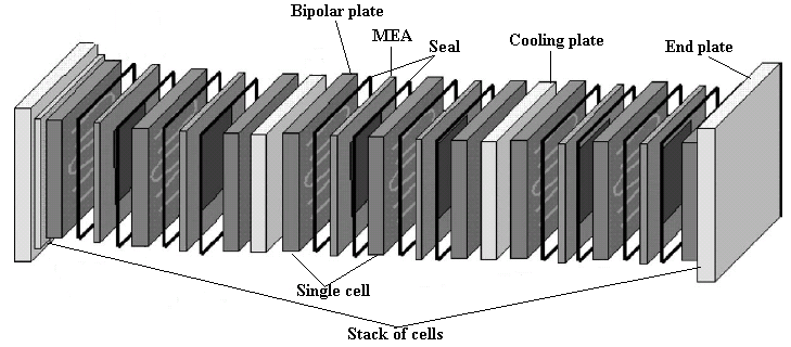 |
| Fig. 6. Exploded view of PEM fuel cell stack. |
System
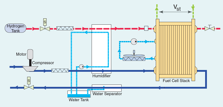 |
| Fig. 7. Schematic of hydrogen PEM fuel cell system. |
- Hydrogen reformer or hydrogen purification. Hydrogen gas rarely occurs naturally on the earth�s surface and has to be made from other chemical fuels. Once the hydrogen fuel is made, impurities such as carbon monoxide poison the cell, necessitating purification and detection systems.
- Air supply. Oxidant must be supplied to the cathode at a specific pressure and flow rate. Air compressors, blowers, and filters are used for this.
- Water management. The inlet reactant gasses must be humidified, and the reaction product is water. Management of water must also consider relative amounts of the two phases.
- Thermal management. Stack temperature must be monitored and controlled trough an active or passive stack cooling systems as well as a separate heat exchanger in the case of an active system.
Balance of plant
The ancillary equipment around the stack used to control the supply of fuel, oxidant, water management, heat management, power management, is called the balance of plant (BOP) or fuel cell system.
Contemporary and well known PEM fuel cell system manufacturers include: Ballard, AFCC, UTC Power (UTC fuel cells, also known as a division of Pratt and Whitney), Plug Power, Hydrogenics, Proton Onsite, Fuji, BASF (PEMEAS USA, E-Tek), WL Gore, Johnson Matthey, Dupont, 3M, Samsung, etc.
Key cell components and materials
Membranes
 |
| Fig. 8. Proton exchange membrane polymers. |
Catalysts and catalyst layers
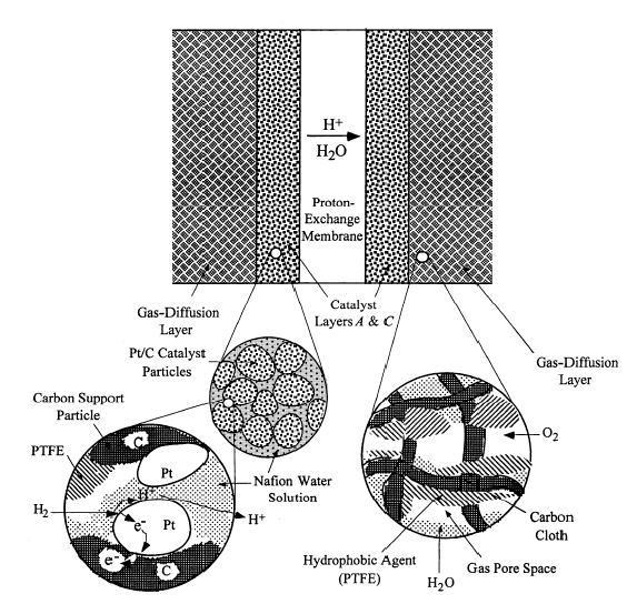 |
| Fig. 9. PEM fuel cell electrode cross section. |
With well-chosen materials, such as catalysts, bipolar plates, backing layers, PEM, and other components including flow fields, and current collectors, an assembled MEA can produce more than 0.5 A/cm2 at 0.7 V with a total thickness of no more than 200 µm.
Gas diffusion layer (GDL)
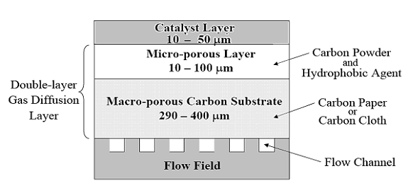 |
| Fig. 10. GDL schematic for PEM fuel cell. |
An ideal GDL has the following characteristics: appropriate hydrophobicity for the application, surface that enhances good electronic contact, low electronic resistance, and effectively transport reactant gases to the catalyst layers.
Membrane electrode assemblies (MEAs)
The MEA is the defining component of a PEM fuel cell. Much like a sandwich, an MEA consists of a gas diffusion electrode made from porous carbon paper or cloth, a micro porous layer, platinum catalyst mixed with ionomer, and the PEM itself, usually Nafion. The same components are repeated on the other side of the PEM, in reverse order. The MEA structure is as shown in Figure 9.
Bipolar plates and flow fields
The bipolar plate is also known as the flow field plate due to the integral design, and it forms one of the more costly and problematic stack components. A key challenge in PEMFC stack development is bipolar plate materials that are both low cost and suitable. Desirable material characteristics include:
- Low cost (<$2/plate);
- Ease of gas flow;
- High electric conductivity (>100 S/cm);
- Low impermeability to gases;
- High manufacturability;
- Reasonable strength;
- Low weight;
- Low volume;
- High chemical stability and low corrosion rate (<16 µA/cm2); and
- Low thermal resistance.
Practical uses of PEM fuel cells (past, present, and future)
PEM fuel cell application
| Table I. PEM fuel cell applications | |
| Level of power | Applications |
| >1 MW | Local distributed power station |
| 100 kW�1 MW | (1) Large transportation vehicles, such as naval ships, submarines, and buses; (2) Small portable power station; and (3) Small stationary power station |
| 10 kW�100 kW | (1) Transportation vehicles such as cars and mid-size buses; (2) Backup power for mid-size communication station; and (3) Small power station |
| 1 kW�10 kW | (1) Transportation vehicles such as motorcycles, utility vehicles, cars, yachts; (2) Various portable power devices used for field working, underwater platform; and (3) Backup power; uninterruptible power, residential power system |
| 100 W�1 kW | (1) Simple riding devices such as bicycles, scooters, and wheelchairs; Backpack power; (2) Power for exhibition or demonstration; (3) UPS for small services, terminals, and computers |
| 10 W�100 W | (1) Portable power such as for emergency working power supply and military equipment; (2) Battery replacements; (3) Lighting; (4) Signal light power; and (5) Laptop computers |
| <10 W | (1) Small portable power device; (2) Cell phone |
Transportation
Since the early 1990�s perhaps the most active and certainly the most publicly visible application has been passenger vehicles and busses. In response to ever more strict air quality regulations, car manufacturers like Ford and VW are investing billions of dollars every year on PEM fuel cell development for hybrid electric, and purely electric vehicles. Additionally, PEM fuel cells have been demonstrated in motorcycles, bicycles, and materials handling equipment (forklifts). Most use pure hydrogen through on board high pressure tanks, however liquid fuels such as gasoline and methanol have also been employed with the use of an on board fuel processor or reformer. Recently, development of on board reforming has diminished due to the added system complexity, weight, risk of PEM fuel cell contamination, and decreased efficiency (relative to operation on pure hydrogen).
Stationary
Combined heat and power for residential and office buildings. Both large scale utility plants and smaller systems, such as those for distributed electricity and heat generation in smaller buildings and individual homes are considered stationary power applications.
Water works, gas suppliers, telecommunication equipment. Other stationary applications include niche markets where the product water and heat are needed, including electronic or communications equipment with strict air and particulate requirements.
Backup power. An instantaneous and uninterruptible power source is a backup device. Typical backup device applications include railways, utility substations, security systems, manufacturing processes, computer systems as well as information technology and telecommunication systems. Backup power sources really have two main criteria: availability and reliability. The power needs to be available at will as well as immediately, and must be available every time it is required. Traditional backup power technologies include internal combustion engine generator sets, and lead-acid batteries. New battery technologies, flywheels, and ultracapacitors then also became part of backup power technology, where the most recent addition is fuel cells. Upon a power outage, all backup power technologies must come on line instantly. For this reason all backup power PEM fuel cell systems operate on hydrogen. One advantage of backup power systems is their lower operational lifetime requirement compared to fuel cell vehicles. At less than 2000 hours, many PEM fuel cells already meet these backup power requirements and thus making this potentially the first market for PEM fuel cell commercialization.
Grid backup power, hospitals, communication, and stations. For hospitals, backup power may also be subject to emission and noise restrictions that perfectly suit a PEM fuel cell�s clean, quiet operation. Other essential communication systems for government or financial offices may have similar requirements, with the added demand in reliability due to the importance of their work.
Portable power
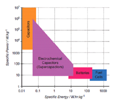 |
| Fig. 11. Ragone plot of specific power against specific energy for various electrochemical energy conversion devices. |
Domestic, medical and military. Other potential applications include powered medical implants where a PEM fuel cell could in theory run continuously. Portable fuel cells can also be used in military, where the solders can carry on with a longer operation time than batteries.
Past uses
The 1950�s and 1960�s saw use of GE�s early PEM fuel cell in the NASA Gemini space program. Early prototype passenger vehicles and busses were built as proof of concept and early demonstrations.
Present uses
PEM fuel cells continue to be demonstrated internationally powering transport (passenger vehicles, busses, forklifts/material handling equipment), stationary (residential combined heat and power), and finally backup (telecommunications, remote power) applications.
Future uses
Micro PEM fuel cells hold much promise for biomedical applications, and bio PEM fuel cells are being explored for use in environmental work (site remediation and power generation). In the near term perhaps the most promising market for PEM fuel cells is backup power, followed by portable power, stationary, and transportation. For transportation and stationary markets, higher activity, lower cost and more durable supported catalysts as well as polymer electrolyte membranes, are being actively researched for use at elevated temperatures and lower relative humidities (RH). There are two target regimes for these next generation PEM fuel cells. The first is lower RH and 95oC (203oF) to 120oC (248oF) operation for transportation markets, and the second is low RH and 160oC (320oF) to 200oC (392oF) operation for stationary markets. The rationale being that higher temperature and lower RH operation allows for simpler water management, higher tolerance to fuel impurities, better heat rejection, and in the case of 120oC (248oF) operating temperatures or higher, the waste heat can be used in cogeneration applications, greatly increasing the overall efficiency. This area is called high temperature PEM (HT-PEM) fuel cells.
Challenges: economics and lifetime
Significant progress has been made since NASA�s Gemini space vehicles were powered by General Electric�s PEM fuel cells. Power increased and cost decreased. However, PEM fuel cells are still too expensive, and their life spans too short for wide spread commercialization. The reaction rates especially for the air or oxygen side are still not fast enough, impurities cause a lot of problems, cooling and water management is still a big challenge, as are both the high cost and low durability of the platinum electrocatalysts. Challenges still remain because as the amount of platinum in the fuel cell decreased with increasing power density, the world market saw the price of platinum increase dramatically. The majority (about half) of a fuel cell�s cost is due to the platinum based catalysts. The tradeoff for having more efficient platinum usage by using finely dispersed platinum on high surface area carbon supports, is the platinum catalyzed chemical oxidation of carbon by oxygen, as well as platinum agglomeration and dissolution. It follows durable or longer lasting catalyst supports are an equally important challenge.
Summary
As chemical energy resources become more difficult to extract, increasing both cost and cost volatility, in turn causing political as well as military instability, not to mention increased pollution and the risk of climate change, electrochemical (photoelectrochemical cell) technologies like PEM fuel cells, that allow production and storage of electricity from diverse fuels at high efficiencies with minimal pollution are a wise investment in terms of energy research, development, and deployment. The following points may be worthwhile to discuss:(1) The current energy infrastructure may face challenges such as fossil fuel depletion, climate change (nitrogen and sulfur oxides, hydrocarbons, particulates, and greenhouse gases); as well as political instability/war related to fossil fuel reserves. In this respect, PEM fuel cells may add value to energy infrastructures. The benefits of this addition could be:
- Reducing dependence on imported crude oil used for passenger vehicles;
- Reducing carbon dioxide emissions to lower the risk of climate change;
- Reducing local air pollution in urban areas;
- Supporting distributed energy sources and electricity distribution;
- Supporting distributed generation, even accelerating electrical grid installation in developing nations;
- Providing electricity and water to remote areas, including drought stricken regions in developing nations;
- Providing electricity, heat and water for commercial and residential applications;
- Enabling renewable electricity market penetration by serving as a buffer to provide continuous power output for variable renewable electricity. Batteries and other fuel cell designs are also able to do this.
(2) Although PEM fuel cell technology has been largely advanced in the last several decades, the cost and durability issues still need to be solved to follow through from research to development, and finally commercial deployment. In addition, the risks and rewards for PEM fuel cells compared to other fuel cells as well as traditional thermochemical processes must be accurately assessed. Relative gains in efficiency, economy, and environmental (three e�s or 3Es) need to be weighed before making conclusions as to the best system, and in turn decisions on what technology to implement
Appendix
Fuel cell electrochemical reactions (Thermodynamics)
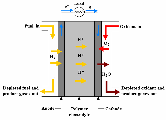
A hydrogen PEM fuel cell operates on two coupled half reactions, that of the hydrogen oxidation reaction (HOR) at the anode, and the oxygen reduction reaction at the cathode (ORR). Other fuels can be oxidized at a PEM fuel cell anode, such as methanol, ethanol, and formic acid. The anode and cathode electrochemical reactions are shown below.
[1] ![]() H2 = 2H+ + 2e-
H2 = 2H+ + 2e-
Where the corresponding anode thermodynamic potential is Eoa = 0.00 V versus SHE (under standard conditions).
[2] ![]() ½O2 + 2H+ + 2e- = H2O
½O2 + 2H+ + 2e- = H2O
Again, the corresponding cathode potential is Eoc = 1.229 V versus SHE (under standard conditions). The overall hydrogen PEM fuel cell reaction is therefore:
[3] ![]() H2 + ½O2 = H2O + heat
H2 + ½O2 = H2O + heat
with the standard equilibrium electromotive force calculated to be 1.229 V.
Oxygen reduction reaction (ORR)
| Table II. Common oxygen reduction electrocatalysts | |||||||
|
Non-noble metal electrodes | Organometallic complexes | |||||
|
|
|
| ||||
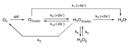 |
| Fig. 12. Different ORR pathways in acid solution. |
Hydrogen oxidation reaction (HOR)
The oxidation of hydrogen on a platinum catalyzed anode is facile relative to the ORR, since it is only a two electron process, and the strength of the single �S� sigma bond is much weaker compared to that of oxygen�s �SP2� pi bond. Hydrogen is stripped of its electrons at the anode, and is adsorbed as a hydrogen cation on the platinum surface. A lower oxidation overpotential and a higher kinetic rate are observed for the HOR on platinum catalysts. However, if the hydrogen is reformed from hydrocarbon fuel, reforming byproducts such as carbon monoxide (CO) will adsorb on platinum active sites, reducing the available platinum surface area, effectively deactivating the catalyst. CO at the trace or parts per million (ppm) level in the gas stream will strongly adsorb on the platinum catalyst at the 10 ppm level, adversely affecting anode performance. High performance PEM fuel cell anode catalysts not only show excellent HOR activity, but also show similar activity in the presence of CO. Such CO tolerant anode catalysts are created when platinum is combined with oxophilic elements which include ruthenium (Ru), tungsten (W), molybdenum (Mo), and tin (Sn). As to why these secondary elements increase the CO tolerance of platinum catalysts, two mechanisms have been proposed. The first is the bifunctional mechanism, and the second is the electronic effect. The current choice for CO tolerant HOR catalysts is platinum/ruthenium, however ternary catalysts have also been researched where the third element is added to promote CO oxidation at lower potentials. Tin (Sn), molybdenum (Mo), tungsten (W), as well as tungsten oxide (WO), iridium (Ir), rhodium (Rh), osmium (Os), and rhenium (Re) all form the third oxophilic component.
Methanol/ethanol/formic acid oxidation
Another type of PEM fuel cell is the direct liquid fuel cell or DLFC where the liquid anode fuel can be methanol (direct methanol fuel cell (DMFC) ), ethanol (direct ethanol fuel cell, DEFC), or formic acid (direct formic acid fuel cell, DFAFC). These DLFC�s are being researched due to their advantages over hydrogen PEM fuel cells. These advantages include: no need for reforming, better heat and water management, and easy storing and handling of the liquid fuel. The lower efficiency of the DLFC lends itself well to portable electronics where energy and power density are more important. Alcohol vapor fuel cells are also being explored.
Heat of reaction
Enthalpy of reaction
The difference between the heat of formation of the reactants and products is known as the heat of reaction. The equation for the reaction of hydrogen and oxygen is exothermic (heat producing), and is the same whether it proceeds by electrochemical or thermochemical routes:
[4] ![]() H2 + ½O2 = H2O + heat
H2 + ½O2 = H2O + heat
The heat of reaction is calculated by subtracting the sum of all the heats of formation of the reactants from those of the products:
[5] ![]()

Where �hf� represents the heat of formation for each reactant. By definition, the heat of formation of any element is zero, while that of liquid water at 25oC (77oF) is �286 kJ/mol, and thus:
[6]![]()

The sign convention states that the heat of reaction for all exothermic reactions is negative. The heat of reaction is given assuming the reactants and products are both at atmospheric pressure and 25oC (77oF) where the product water will be in liquid form. Also known as hydrogen�s heating value, the enthalpy of hydrogen combustion is known as the higher heating value (HHV) if liquid product water is produced trough exact stoichiometric amounts of hydrogen and oxygen. If however, the oxygen is supplied in excess, the heat of combustion of hydrogen is known as the lower heating value (LHV) with a value of -242 kJ/mol.
Gibbs free energy
Similar to the change in enthalpy of a reaction, as well as the heat of combustion, the change in Gibbs free energy of a reaction is the difference between the sum of Gibbs free energies of the products and reactants. The sign convention is the same as that for enthalpy, where a negative Gibbs free energy denotes energy released from the reaction. For the reaction of hydrogen with oxygen, this is written as:
[7] ![]()

[8] ![]()

Where �Gf� represents the Gibbs free energy of formation. Gibbs free energy is affected by temperature and pressure as noted below:
[9] ![]()

where �R� is the universal gas constant (8.314 J/(kg K)), �T� is the temperature in degrees Kelvin (K), �pH2�, �pO2�, and �pH2O� are the partial pressure of the hydrogen, oxygen, and water vapor, respectively, and � ΔGfo � is the change in Gibbs free energy under standard conditions.
Reversible fuel cell potential
If all the Gibbs free energy could be converted to electrical energy, then the fuel cell reaction is said to be reversible. Then the change in Gibbs free energy of the reaction is related to the voltage of the fuel cell by the equation:
[10] ![]()

where �n� is the number of electrons per mole transferred in the reaction, �F� is Faraday�s constant (96485 C/mol), and �E� is the fuel cell�s reversible (or Nernst) voltage. Electrical work (charge × voltage) is the physical meaning of �-nFE�. More common names for �E� are the thermodynamic potential, or reversible fuel cell potential. Substituting for �ΔG� in Equation [9] above, one obtains the Nernst Equation for a hydrogen and oxygen fuel cell:
[11] ![]()

where terms are as described before. Now �E� is also called the Nernst voltage or potential. Note that the electron number (n) in Equation [11] is equal to two because each hydrogen molecule can give two electrons in the fuel cell reaction and consumes a half mole of oxygen for each mole of hydrogen reacted.
Fuel cell efficiency
Carnot efficiency
Since the law of conservation of energy states that energy cannot be created or destroyed, efficiency is a measure of usable energy output, compared to the total energy input of a given system. Most energy conversion devices based on thermochemical processes, such as combustion as well as steam turbines, are called heat engines. The efficiency of a heat engine is called the Carnot efficiency, where the theoretical Carnot efficiency of a heat engine (ηeff) is given by:
[12] ![]()

where �T2� is the temperature of the heat sink, typically no lower than room temperature (295 K), and �T1� is the temperature of the heat source. Commonly �T2� is fixed at 50oC (122oF) or 323 K and �T1� for a typical steam turbine is 400oC (752oF) or 673 K. Thus the maximum thermodynamic efficiency for the steam turbine is:
[13] ![]()

In reality losses due to friction, heat exchanger fouling, and other irreversibilities lead to operating thermodynamic efficiencies lower than 52%. Some energy is thus always unusable, or wasted in any energy conversion device.
Theoretical fuel cell efficiency
 |
| Fig. 13. Thermodynamic efficiencies of hydrogen/oxygen fuel cell and a heat engine. |
[14] ![]()

As the enthalpies and Gibbs free energies of reaction are temperature dependent, the thermodynamic efficiencies of a fuel cell and heat engine can be plotted as a function of temperature at a given pressure. A comparison of these two efficiencies with temperature and at 25oC (77oF) is shown in Figure 13.
Thermodynamic energy conversion efficiency for fuel cells
Just as the actual Carnot efficiency of a heat engine never attains the thermodynamic limit, the same is true for fuel cells. The actual efficiency of a fuel cell is simply the cell voltage (Vcell) divided by the thermodynamic potential (either based on the HHV or LHV). The corresponding equations are:
[15] ![]()

[16] ![]()

In an operating fuel cell, some of the fuel is unreacted, and the fuel that is not consumed adds another efficiency factor called the fuel utilization coefficient (ηf) which is defined as:
[17] ![]()

Correspondingly, the fuel cell efficiency is then:
[18] ![]()

[19] ![]()

Fuel cell reaction kinetics
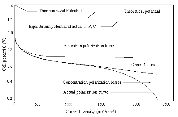
Polarization and voltage loss
Polarization. Because of polarization, the operating voltage of a fuel cell is always less than that of the open circuit voltage (OCV). The actual fuel cell voltage is simply called the cell voltage (Vcell), and the cell current (I) divided by the cell unit active area (A) is called the current density (i):
[20] ![]()

Because they are connected in series, the stack current is the same as the cell current. As soon as the fuel cell circuit goes from �open� to �closed�, the OCV immediately decreases as the electrodes polarize. The decrease in cell voltage, termed voltage loss, results when the respective anode and cathode potentials shift away from their equilibrium potentials, to more positive and negative ones, respectively.
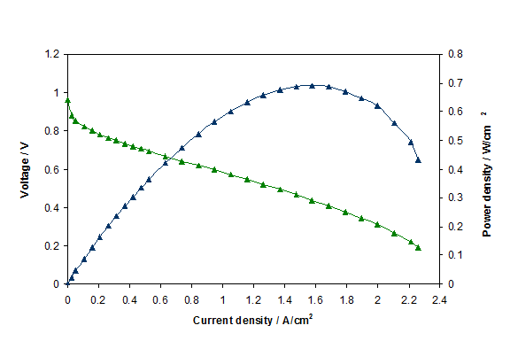 |
| Fig. 14. Polarization curve for a PEM fuel cell. |
 |
| Fig. 15. Polarization losses for a PEM fuel cell. |
[21] ![]()

Activation loss. Activation polarization is caused by current flow, and thus a shift away from the equilibrium position of the anodic and cathodic half reactions in turn causes activation overvoltage or activation loss. The total activation overvoltage �ΔVact� is the sum of the anodic and cathodic losses (ηa and ηc):
[22] ![]()

The Tafel equation then describes the relationship between activation overvoltage and current density:
[23] ![]()

Where �a� and �b� are the Tafel intercept and slope, respectively. Between the HOR and ORR the relatively sluggish kinetics of the ORR mean that the cathodic voltage drop dominates activation overvoltage where:
[24] ![]()

Where �αO2� is the electron transfer coefficient, �nα,O2� is the electron transfer number in the rate determining step of ORR, �i0,O2� is the ORR exchange current density, and �R�, �T�, and �F� have their usual meanings. If an anodic fuel other than hydrogen is used, then the voltage drop at both electrodes must be considered. At higher operating temperatures and pressures, activation overvoltages seem less important.
Ohmic losses. Resistance of the electrolyte to ion transfer, and of both the electrode and collector plate to electron transfer causes ohmic polarization, or ohmic loss. As the name implies the ohmic overvoltage is dictated by Ohm�s law:
[25] ![]()

Ionic, electronic, and contact resistances all sum to form the ohmic resistance �Rohm� (Ωcm2). AC impedance and current interruption can distinguish ohmic overvoltages from other types of resistance.
Mass transport losses. If the reactants are being consumed faster than they can be supplied, the concentration decreases whereby the rate, and thereby voltage produced at a fixed current density, is limited by the concentration of a reactant. The resulting concentration polarization will cause concentration loss or concentration overvoltage, and a rapid drop in cell voltage at high current densities. This loss is expressed as:
[26] ![]()

Where �ΔVcon,a� and �ΔVcon,c� are the anode and cathode mass transfer voltage losses, respectively. They can be expressed as the functions of anode and cathode limiting current densities, respectively. Then the mass transfer loss (or concentration losses can be expressed as Equation [27]:
[27] ![]()


Lastly, there are other losses caused by fuel crossover from the anode, resulting in a mixed potential at the cathode and also caused by internal currents. Fuel crossover and internal currents have an effect on the cell�s �VOCV�
In summary:
[28] ![]()

where:
[29] ![]()


Measures to improve cell performance
Minimizing activation loss. The exchange current densities of both anode HOR and cathode ORR (i0,H2 and i0,O2), are essential in minimizing activation overvoltage, in particular that of ORR. This is accomplished by increasing exchange current density trough the following techniques:
- Increasing cell temperature;
- More active or effective catalysts;
- Increasing electrode roughness, thereby increasing electroactive surface area;
- Increasing reactant concentration; and
- Increasing operating pressure.
Minimizing ohmic losses. The internal resistance of the cell can be reduced by:
- High conductivity electrodes;
- Efficient design and ideal materials for cell interconnects and bipolar plates; and
- Minimizing electrolyte thickness without sacrificing cell structural integrity or impeding electrolyte flow.
Minimizing mass transport losses. Mass transport of reactants can be increased by:
- Increasing reactant concentration;
- Increasing reactant flow rate and or pressure;
- Optimizing flow field design; and
- Improving gas diffusion layer (GDL) structure and optimizing its porosity.
Acknowledgements
Related articles
Fuel cellsMicro fuel cells
Nonrechargeable batteries
Solid-oxide fuel cells
Bibliography
- Electrochemical Impedance Spectroscopy in PEM Fuel Cells - Fundamentals and Applications, X. Z. Yuan, C. Song, H. Wang, and J. Zhang, Springer, London, 2010.
- Proton Exchange Membrane Fuel Cells: Materials Properties and Performance, D. P. Wilkinson, J. Zhang, R. Hui, J. Fergus, and X. Li (editors), CRC, Boca Raton, FL, 2010.
- Proton Exchange Membrane Fuel Cells: Contamination and Mitigation Strategies, H. Li, S. Knights, Z. Shi, J.W. Van Zee, and J. Zhang (editors), CRC, Boca Raton, FL, 2010.
- Iron-Based Catalysts with Improved Oxygen Reduction Activity in Polymer Electrolyte Fuel Cells, M. Lefevre, E. Proietti, F. Jaouen, and J. P. Dodelet, �Science� Vol. 324, pp 71-74, 2009.
- PEM Fuel Cell Electrocatalysts and Catalyst Layers - Fundamentals and Applications, J. J. Zhang (editor), Springer, London, 2008.
- A Class of Non-Precious Metal Composite Catalysts for Fuel Cells, R. Bashyam, and P. Zelenay, �Nature� Vol. 443, pp 63-66, 2006.
- Activity Benchmarks and Requirements for Pt, Pt-Alloy, and Non-Pt Oxygen Reduction Catalysts for PEMFCs, H. A. Gasteiger, S. S. Kocha, B. Sompalli, and F. T. Wagner, �Applied Catalysis B: Environmental� Vol. 56, pp 9-35, 2005.
- Control of Fuel Cell Power Systems: Principles, Modeling, Analysis, and Feedback Design, J. T. Pukrushpan, A. G. Stefanopoulou, and H. Peng, Springer, London, 2004.
- Quantum Jumps in the PEMFC Science and Technology from the 1960s to the Year 2000: Part I. Fundamental Scientific Aspects, P. Costaminga, and S. Srinivasan, �Journal of Power Sources� Vol. 102, pp 242-252, 2001.
- Low Cost Electrodes for Proton Exchange Membrane Fuel Cells, T. R. Ralph, G. A. Hards, J. E. Keating, S. A. Campbell, D. P. Wilkinson, H. Davis, J. St-Pierre, and M. C. Johnson, �Journal of the Electrochemical Society� Vol. 144, pp 3845�3857, 1997.
- Electrocatalysis of Aqueous Dioxygen Reduction, A. J. Appleby, �Journal of Electroanalytical Chemistry� Vol. 357, pp 117-179, 1993.
Listings of electrochemistry books, review chapters, proceedings volumes, and full text of some historical publications are also available in the Electrochemistry Science and Technology Information Resource (ESTIR). (http://knowledge.electrochem.org/estir/)
The Encylopedia is hosted by the The Electrochemical Society, Inc. (ECS).
Copyright Notice.
Maintained by
Zoltan Nagy (
nagyz@email.unc.edu ),
Department of Chemistry,
The University of North Carolina at Chapel
Hill.
Return to: Top – Encyclopedia Home Page – Table of Contents – Author Index – Subject Index – Search – Dictionary – ESTIR Home Page – ECS Home Page