|
|||||||||||||||||||||||||||||||||||||||||||||||||||||||||||||||||||||||||||||||||||||||||||||||||||||||||||||||||||||||||


 |
 |
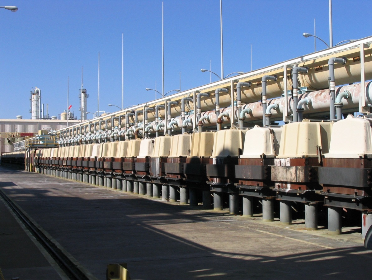
| Fig. 8. Chlor-alkali cell line with MDC-55 diaphragm cells (Courtesy of Occidental Chemical Corporation). | Fig. 9. Chlor-alkali cell line with BL-2.7 membrane cells (Courtesy of Uhde GmbH). |
 Monopolar or bipolar configuration
 |
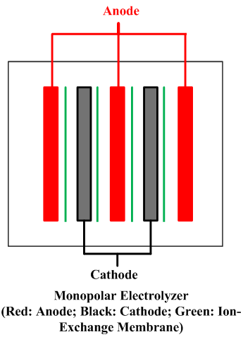 |
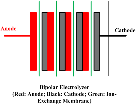
| Fig. 10. Bipolar and monopolar arrangements. | |
A disadvantage of electrolytic production is the low space-time yield of the reaction process. Plot area requirements may be much greater than those of other types of chemical reactor. Thus, a square meter of electrode may produce about 200 kg/day of caustic soda. Many cells are necessary in a large plant. It is customary in design to assemble a number of electrodes in a body frequently referred to as a �cell� but sometimes more accurately as an �electrolyzer� comprising a number of cells. A number of electrolyzers then may be connected in electrical series and served by dedicated rectifiers. Some plants will have more than one line of electrolyzers.
A cell line therefore usually contains a number of electrolyzers, each holding a number of cells or at least of separate electrodes. Interconnecting these electrically and attaching them to the terminals of a rectifier form a circuit. There are two fundamentally different ways to do this, as shown in Figure 10. In a bipolar arrangement, an electrode structure is anodic on one side and cathodic on the other. The cells in a given electrolyzer are connected to each other, anode to cathode. The connection is direct, metal to metal, perhaps with the aid of conductive strips. In a monopolar arrangement, any given electrode structure will have a single polarity. It will be either anodic or cathodic and will be at substantially the same voltage as other electrodes of the same polarity in the same electrolyzer. The anodes in one electrolyzer will be connected to cathodes in adjacent electrolyzers. The cells are electrically in parallel, rather than in series, as they are in a bipolar arrangement.
Monopolar electrolyzers therefore normally operate at high current and low voltage drop. Bipolar electrolyzers have the opposite characteristic, and an electric circuit may contain only one electrolyzer. Bipolar electrodes have more demanding requirements for materials selection and therefore the disadvantage of more complex structure. Monopolar electrodes require external intercell electrical connectors in the form of bus bars, cables, straps, or the like.
All operating mercury cells are monopolar. Diaphragm cells with a few exceptions likewise are monopolar. Membrane cells of both types are in operation. The ability to increase current densities in membranes has caused a trend to bipolar designs. With monopolar cells, the energy loss due to intercell connectors and the complications of their attachment to electrodes become more and more problematic as the current on an electrode increases. The electrolyzers shown in Fig. 8 are bipolar. Another advantage of a membrane cell installation is that it requires less floor area than either of the other types.
Other types of cells
In mercury and membrane cells, a small percentage of chlorine is made from potassium chloride. The coproduct then is potassium hydroxide rather than sodium hydroxide. Other processes not based on brine produce chlorine without caustic. Electrolysis of hydrochloric acid, for example, produces only chlorine and hydrogen. Cells are bipolar, classically using graphite electrodes and PVC diaphragms. The electrolyte contains about 20% hydrochloric acid. Recent developments include the use of ion-exchange membranes, depolarized cathodes, and alternative diaphragms. Other metal chlorides, anhydrous or nearly so, are the source of their metals as well as gaseous chlorine. For production of sodium, the chloride actually is mixed with calcium chloride to reduce the melting point. Electrolysis is at temperatures approaching 600�C (1100oF). Diaphragms of iron gauze separate cylindrical graphite anodes from steel cathodes. Details of magnesium chloride electrolysis vary more, depending on the choice of raw material. Again, anodes are graphite and cathodes are steel.
Chlorine processing
The chlorine gas from the cells contains water, by-product oxygen, oxygen and nitrogen from air leakage and process usage, and some back-migrated hydrogen. With alkaline feed brine, it will also contain carbon dioxide.
Chlorine gas is first cooled to about 16oC (60oF)and then passed through demisters to remove water droplets and particulate salt and sodium sulfate. The cooled gas goes to sulfuric acid circulating towers to remove moisture. Commonly, there are three towers in series. The dried chlorine then goes through acid demisters before compression and liquefaction at low temperatures. Much of the chlorine used on site does not require liquefaction. The liquefied form is easier to store and transport. In some cases, liquefaction also provides a stage of purification by rejecting impurities. The non-condensed gas, called snift gas, can be used to produce hypochlorite or hydrochloric acid. Uncondensed gas from liquefaction may be joined by smaller process vents and by intermittent flows from maintenance activity, returned shipping containers, and the like. If there is no market for hydrochloric acid, the snift gas is neutralized with caustic soda or lime (calcium hydroxide) to form hypochlorite. The hypochlorite is either sold as bleach or decomposed to form salt and oxygen.
Hydrogen processing
The hydrogen gas from chlor-alkali cells may be used to produce hydrochloric acid or used as a fuel to produce steam. Hydrogen from mercury cells is first cooled at the cells, condensing vaporized mercury for return to the cells. Occasionally, the gas is treated to remove the last traces of mercury. The hydrogen gas is then normally compressed. If a customer needs a low concentration of oxygen, producers may heat the hydrogen over a platinum catalyst to remove the oxygen. The sensible heat in the hydrogen cell gas can be recovered by exchange with the feed brine.
Caustic soda processing
Caustic soda is marketed as 50% or 73% solution and as dry beads or flakes. Mercury cells normally produce 48-50% sodium hydroxide for direct application or sale. With some added difficulty and increased energy consumption, they also can produce 73% caustic directly. The caustic from the decomposer is cooled and passed once or twice through activated carbon filters to remove mercury. This reduces the mercury concentration to parts per million (ppm) levels. Even these low levels may be unacceptable to some customers, who then may switch to membrane-grade caustic soda. The mercury cell caustic soda has a few ppm salt and less than 5 ppm sodium chlorate. This is the highest purity that can be made electrolytically if trace concentrations of mercury are tolerable in the end use of caustic.
Membrane-cell caustic is concentrated to 50% in a multiple-effect evaporator. The product generally has 30 ppm sodium chloride and 5-10 ppm sodium chlorate.
Diaphragm-cell catholyte contains 10-12% sodium hydroxide, 14% sodium chloride, 0.25%-0.3% sodium sulfate, and 100-500 ppm sodium chlorate. It is concentrated to 50% sodium hydroxide in a multiple-effect evaporator. The evaporative load is much higher than in the membrane process. Diaphragm-cell evaporators therefore normally have more effects (three or four) than membrane-cell evaporators (two or three). Most of the salt is precipitated during the process. After recovery on centrifuges, it is used to resaturate the brine fed to the cells. After cooling, the 50% caustic soda product will contain about 1% sodium chloride. It also has a higher chlorate concentration (~0.1%) than caustic from membrane or mercury cells (~10 ppm). An additional single-effect evaporator can be used to produce 73% caustic soda. �Dry� caustic soda (97-98% sodium hydroxide) is produced in an evaporator heated by a molten salt and operating at 385oC (725oF). The product is suitable for production of cast or flaked solid. Evaporative flash cooling at pressures below about 4 pound per square inch gives 99.5% sodium hydroxide. This is suitable for production of beads and offers improved physical properties and easier handling.
Brine processing
Sodium chloride is supplied in the form of solid salt, mined by excavation or crystallized from evaporating seawater. It is also available in liquid form from solution mining of rock salt deposits. The salt has varying concentrations of impurities, which must be removed to operate the electrolytic cells at a high current efficiency. The major impurities are calcium, magnesium, and sulfates. Minor impurities include barium, strontium, manganese, aluminum, silica, iron, vanadium, chromium, molybdenum, titanium, etc.
The solution-mined brine or dissolved salt is treated in a reactor with sodium carbonate and caustic soda to precipitate calcium carbonate and magnesium hydroxide (see the Appendix). These precipitates form a thin underflow from a settler. This can be filtered to remove the solids as a cake or as a more concentrated sludge. Sometimes, it is disposed of along with the rest of the liquid effluent from the plant. The calcium carbonate precipitate is heavy and drags with it the hydroxides of aluminum, magnesium, strontium, etc. The overflow from the settler, which carries 10-50 ppm of suspended solids, is filtered. In the mercury and the diaphragm cell processes, this brine is acceptable as feed to the cells.
In all cell processes, the filtered brine is heated and passed through a bed of salt in a saturator in order to increase its salt concentration before feeding it to the electrolyzers. In some plants, the brine feed is acidified to improve the cell current efficiency. The acidification reduces the alkalinity, which would otherwise react with the chlorine in the anolyte compartment, forming chlorate.
Membrane cell brine specifications are more stringent than those of the other processes. Hardness impurities must be at the parts-per-billion (ppb) level. This is accomplished first by filtering the brine in a pre-coat type secondary filter. An ion-exchange resin then is used to remove the calcium, magnesium, strontium, barium, and iron impurities. It is also possible to remove aluminum by ion exchange. Often, aluminum and silica are removed by adding magnesium chloride to the brine leaving the salt dissolver.
The depleted brine from the membrane and mercury cell processes carries dissolved chlorine. This brine is acidified to reduce the chlorine solubility and then dechlorinated under vacuum. The dechlorinated brine returns to the brine wells for solution mining or goes to the salt dissolver. If membrane and diaphragm processes coexist at a given location, the dechlorinated brine can go to a saturator for resaturation before being sent to the diaphragm cells. The membrane process requires very low levels of free chlorine in the brine. Vacuum dechlorination then is followed by a secondary process in which the chlorine is chemically reduced to chloride ion.
Sodium chlorate manufacturing process
Sodium chlorate is produced from sodium chloride solution in an electrolytic cell without a separator. The electrode products, chlorine and caustic soda, are allowed to intermix and react, giving sodium chlorate as the final product (see the Appendix for details).
Sodium chloride is provided as solar salt, rock salt, or purified evaporated salt. The brine may be purified by removing calcium, magnesium, fluoride, sulfate, and iron as insoluble compounds, typically through the addition of sodium carbonate, sodium hydroxide, sodium phosphate, and barium chloride.
Precipitates are removed by filtration, normally in a pressure-leaf filter with the addition of precoat and filter aid. The filter cake is the major solid waste stream from the process. A polishing filtration stage and an ion-exchange system similar to those used in chlor-alkali brine treatment follow filtration. This reduces hardness to parts per billion (ppb) levels and improves electrode performance.
The chemistry of chlorate formation requires a process with several distinct zones. In the electrolysis zone, the electrolytic reactions take place along with the hydrolysis of chlorine to form hypochlorite. Chemical chlorate formation from the �hypo� is relatively slow and requires a sufficient volume of chemical reaction zone. A cooling zone removes excess heat and controls the operating temperature. Cooling may take place within the chemical reactor or in an external heat exchanger. Hydrogen gas generated at the cathode must be released from the cell liquor. This hydrogen release takes place in the electrolysis cell, the chemical reactor, or a separate vessel.
A continuous stream of cell liquor flows from the electrolysis system to the hypo removal system, where the sodium hypochlorite concentration is reduced to low levels simply by heating the cell liquor to about 85-95oC (185-200oF) under pH control. Final traces of hypochlorite can be removed by adding a reducing agent such as sodium sulfite or hydrogen peroxide.
Sodium chlorate is usually recovered from cell liquors by evaporative crystallization. Hot cell liquor, after hypo removal, is fed continuously into an evaporator/crystallizer. Crystal slurry is withdrawn from the bottom of the crystallizer section. The crystals are separated from the mother liquor and washed with water. Washing also removes sodium dichromate, an additive to the cell solution to increase current efficiency, from the crystals. This improves the purity of the final product. Specifically, it is also important to remove hexavalent chromium, a recognized carcinogen. A white sodium chlorate crystal, containing 1 to 1.5% moisture, results. After drying, the product is ready for storage or shipping. Mother liquor is mixed with fresh purified brine and recycled to the cells.
Gases from both the anode and the cathode leave a cell together. This means that the hydrogen must be scrubbed by an alkaline liquor to remove chlorine before it is used or vented from the process. It is also monitored for its oxygen content in order to prevent accumulation of dangerous concentrations.
It is worth noting that production of caustic potash (potassium hydroxide) requires simply the use of potassium chloride rather than sodium chloride in the electrolytic process. Potassium chlorate, however, normally is made by adding potassium chloride to sodium chlorate cell liquor, a mixture of sodium chloride and sodium chlorate. Double decomposition of the latter with potassium chloride gives sodium chloride and potassium chlorate. The latter is recovered by precipitation.
Approximately 98% of sodium chlorate is produced electrolytically. The remaining 2% is produced "chemically" by the reaction of chlorine and caustic soda (see reaction 14 in the Appendix).
Sodium hypochlorite manufacturing process
Hypochlorite cells are similar to those used for chlorate manufacture in that they contain no separator or diaphragm. The electrode reactions are the same as in chlor-alkali and chlorate cells. The electrode products are free to mix and form hypochlorite. In the chlorate process, the apparatus and conditions are designed to promote the chemical transformation of hypochlorite to chlorate. In a hypochlorite cell, the opposite is true. Since the hypochlorite ion formed in bulk is easily reduced to chloride at the cathode, only dilute solutions of bleach can be produced in a hypochlorite cell. Chlorate formation is minimized by keeping the solution basic (pH 10 to 12) and the temperature low.
The material fed to the cell can be dilute brine prepared from salt or even seawater. The product of the latter is used for marine sanitation and as a biocide in desalination plants. Concentrations of active chlorine are well below 1%. The process is very simple and normally operates at the point of use, but conditions are not ideal for electrolysis. Using weak brine prepared from high-quality salt and softened water, consumptions per kilogram of chlorine produced may be about 2.5 kg sodium chloride and 4.4 kWh.
More concentrated hypo results when a standard chlor-alkali cell is used to produce chlorine and caustic soda and then the two products are combined to produce hypo chemically. Cell performance improves, but the process becomes more complex. Taking this a step farther and outside the realm of electrolysis, one can also purchase the raw material chlorine and caustic from merchants. Use of concentrated sodium hydroxide requires the addition of dilution water to the process. Industrial strength product is limited to 16% (weight/volume) active chlorine. Decomposition of the product is a potential problem, but the special conditions necessary in chemical processing and product handling are beyond the scope of this article.
There is a trend towards the use of hypochlorite bleach solutions in place of elemental chlorine in public water supply systems. Shipping and handling operations are considered safer. This is part of a general reduction in the amount of chlorine transported as such between sites.
Market growth
Chlor-alkali industry
After World War II, the world economy was growing and the synthetic chemicals business was beginning to make its mark. Chlorine, as a key element in many syntheses, found many new markets. Demand grew at a rate of 8% per annum through the 1950�s and 1960�s. Some individual markets, for example, PVC and ethylene and propylene oxides, grew at rates of 10-15% per annum. In the 1970�s, environmental concerns began to affect some applications, and through the 1980�s there was little growth. The substantial markets in pulp and paper, fluorocarbons, and chlorinated solvents have all but disappeared.
From about 1975 to 2000, there was little growth in chlorine demand in North America and Europe. Many markets were mature, those noted above were declining or even disappearing because of environmental problems, and developing countries were seeking indigenous supplies. Around the turn of the century, most of the world was in economic crisis. The electrolytic industries, like many others, contracted. In the last few years, the economy has recovered and durable goods are seeing a strong increase in demand. Worldwide, chlorine consumption has been growing at about 4% per annum.
The North American industry is growing at a faster rate. The energy situation in this part of the world has improved greatly with the availability of relatively cheap shale-based gas. In particular, this development supports a strong export market for vinyls and other derivatives.
Chlorate industry
Chlorine dioxide has long played a role in the bleaching of wood pulp. Its great oxidizing power combined with its 263% available chlorine helps to offset its higher cost. With the discovery of small quantities of dioxins in pulp mill effluents, there came a wave of regulations against the use of elemental chlorine in pulp bleaching. The demand for chlorine dioxide, as a replacement, therefore grew rapidly through the 1980�s and 1990�s. Sales of its precursor, sodium chlorate, followed along. This shift is essentially complete in North America and Europe. In recent years, there has been much rationalization in the chlorate industry. Changes are driven by technology and energy costs.
Other parts of the world are increasing their share of the pulp market, and there the consumption of sodium chlorate continues to increase. In China, for example, the chlorate market is growing more than 10% per annum. Russia is exploiting its vast forest reserves at a greater rate, especially with soft woods. Chlorate consumption follows along. It faces competition from hydrogen peroxide and oxygen bleaching. There is also an increase in the demand for brighter paper, and this adds to the demand for chlorine dioxide. The other markets for sodium chlorate are quite small in relation to pulp bleaching and contribute little to the overall picture.
Environmental issues within the chlor/alkali industry
Environmental concerns have influenced the chlor-alkali industry over the past several decades and will affect future growth as well. Some have been alluded to in the text above. Several issues that have been vigorously debated are discussed more thoroughly below.
Chlorine bleaching of wood pulp and dioxin emissions to the environment
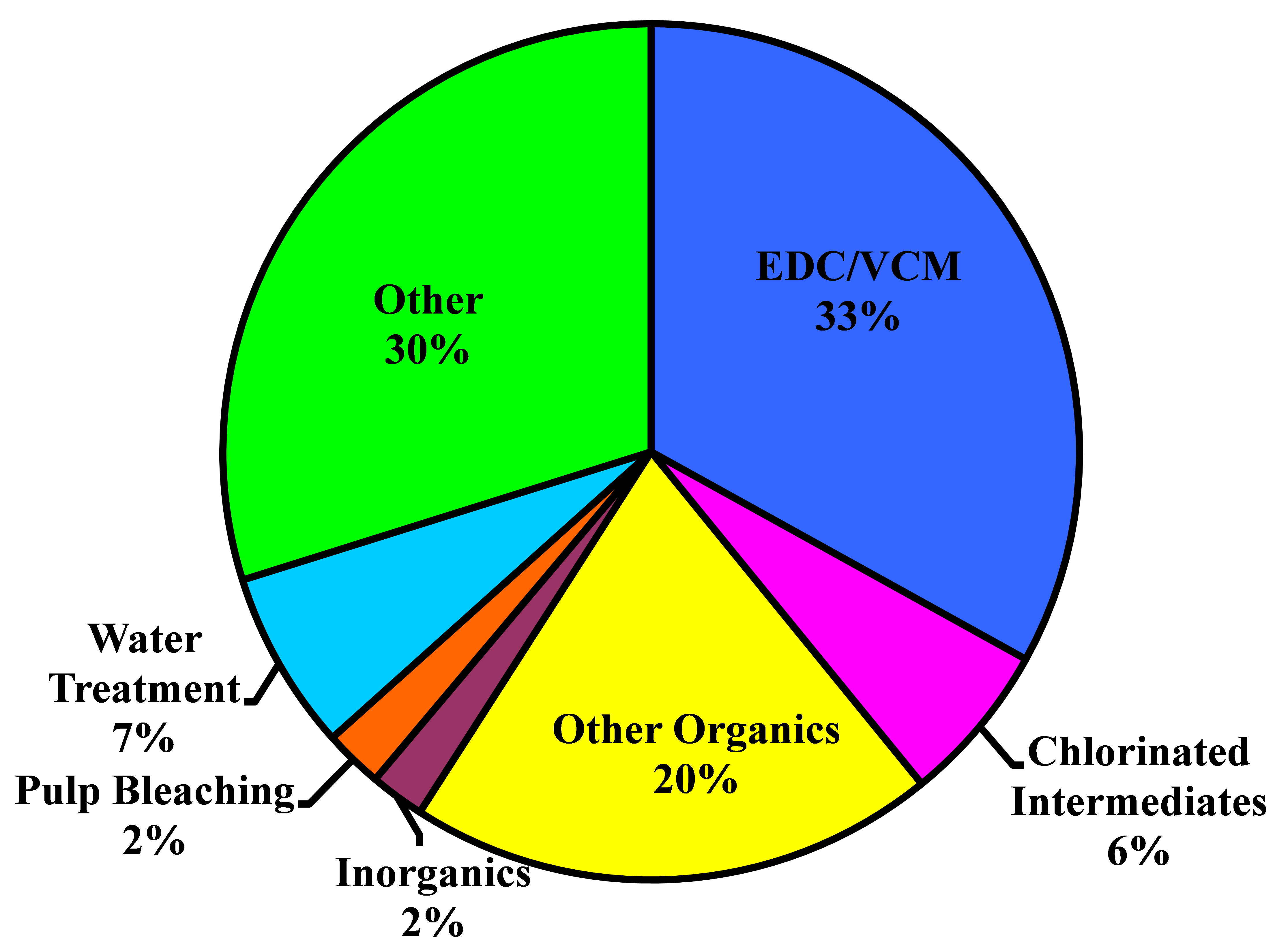
The presence of dioxin at parts per trillion levels in paper and paper-based products and in chlorinated organics in pulp mill effluents has decreased the use of chlorine as a bleaching agent in the pulp and paper industry. From 15% of the total US chlorine market in 1987, this industry�s demand declined to 7% in 1998. The U.S. Environmental Protection Agency then promulgated its "Cluster Rules" in late 1998, mandating the use of elemental chlorine-free (ECF) bleaching. These rules took effect in 2001. Other countries have followed similar paths. As a result, elemental chlorine has all but disappeared from this market. It has been replaced primarily by chlorine dioxide, hydrogen peroxide, and oxygen.
Ozone layer depletion
Chlorinated fluorocarbons (CFC's) and hydrochlorofluorocarbons (HCFC�s) formerly were major consumers of chlorine. Their principal uses were in refrigerants, propellants, and chemical intermediates. They were produced by reacting chlorine derivatives with HF. Insertion of an atom of fluorine in a CFC or HCFC therefore required prior consumption of chlorine. This market began to disappear after adoption of the Montreal Protocol (1987) to combat the depletion of the ozone layer by CFC�s. Carbon tetrachloride, methyl chloroform, and some other chlorinated organics have been phased out for the same reason. For practical reasons, HCFC�s were the first substitutes for CFC�s as refrigerants and aerosol propellants. Replacement was fairly rapid, and the concentration of CFC�s in the atmosphere is now declining. HCFC�s are imperfect replacements, because they have an ozone depletion potential of their own. It is because this is usually less than 10% of the ozone depletion potential of an equal weight of CFC that the replacement program has been successful. HCFC�s are in turn being replaced with hydrofluorocarbons, which have no ODP. Choice of agents now depends on their global warming potential as well. Chemical applications still provide a market for some fluorochemicals. HCFC-22, as an example,is much less harmful than the CFC's towards ozone depletion and is an intermediate in the production of tetrafluoroethylene for use in fluoropolymers.
Polyvinyl chloride plastic
Environmental issues with PVC are its poor biodegradability and the generation of hydrochloric acid and dioxins during its incineration. Improvements in waste handling and incineration practice have reduced emissions from that source. Still, these problems have caused the substitution of chlorine-free products for PVC in some cases. The recycle of PVC products is another response to the problem. In 2012, Euro Chlor reused 360,000 tons of PVC. The goal for 2020 is 800,000 tons.
Mercury emissions
Between 1930 and 1960, several tons of mercury compounds were dumped into Japan�s Minamata Bay. Thousands of people living around the bay developed methylmercury poisoning through the consumption of contaminated fish. Some victims suffered severe neurological damage, which later became known as Minamata Disease. The increased recognition of the hazards of mercury has caused a significant move away from mercury-cell technology, first to diaphragm- and then to membrane-cell operation, and currently less than 10% of the world capacity uses the mercury-cell process. There will be no new construction of mercury-cell plants. One can expect the existing plants to continue to shut down or convert to membrane technology. There are a few plants that react amalgam with something other than water to produce specialties. These may survive longest.
Existing plants are focusing on operating their plants at lower than the goal of 1.0 gram/ton of chlorine capacity set by the Euro Chlor Best Available Technique program. The weighted average in 2010 was 0.88 gram/ton. The largest and most difficult category is emission to the air. Chlorine cell lines require outdoor construction or high rates of ventilation to prevent excessive ambient temperatures. Treatment of the air is impracticable, and the effort instead is to build tighter systems and modify maintenance procedures to reduce vaporization.
There has always been a problem in reconciling measured emissions with the amount of mercury brought into a plant. In-process inventory can be measured by using radioactive mercury as a tracer. The precision of this method is estimated to be 0.5-1%. The uncertainty amounts to 10-20 years� worth of emissions. This accounts for variability but does not explain the fact that emission measurements are predominantly lower than mercury purchases. One known reason for the difference is the ongoing accumulation of mercury in the plant (for example, in tank bottoms and by amalgamation with metals). Still, the difference frustrates programs for mercury control. In recent years, operators have placed more emphasis on smaller details, reduced fugitive emissions, increased the recovery of mercury, and formalized standard methods for inventory measurement. The so-called �difference to balance� has decreased from 46 gram/ton in 1977 to an average of about 3 gram/ton over the last decade.
Asbestos
Asbestos classically was used as the separator material in diaphragm cells. Technological improvements, beginning in the 1970�s, led to the use of polymer-modified diaphragms. In these, asbestos is mixed with fibers of a fluoropolymer which is fused after being deposited on the cathodes. However, asbestos is a toxic material, causing asbestosis and lung cancer. As a result, many countries decided to ban most uses of asbestos. Chlor-alkali plants generally were exempt because practicable alternatives did not exist. More recently, outright bans or end-dates for the use of asbestos have become common, and its use is at least discouraged. Euro Chlor-BAT, for example, does not recognize the use of asbestos in any form. Partly as a result of this, many diaphragm-cell plants have converted to membrane-cell technology. The remaining diaphragm-cell plants comprise about 25% of the world�s capacity. Some have adopted synthetic diaphragms that contain no asbestos. They generally are based on polytetrafluoroethylene. Some (Polyramix) have zirconium oxide additives; some (Tephram) contain the ion-exchange polymer used in membranes. Besides eliminating the asbestos problem, these diaphragms offer longer useful life and lower operating voltage. The latter translates into lower operating cost or the ability to increase production without increasing electrical supply.
Chlor/alkali manufacturing process
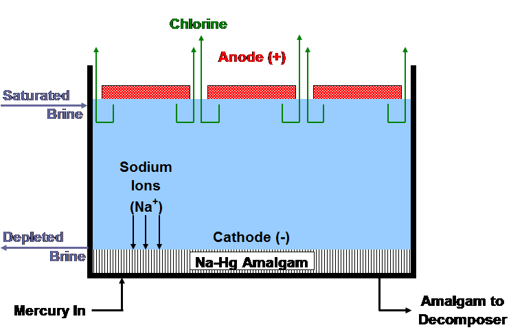
Electrochemical and chemical reactions occurring in mercury cells
| [1] | 2Cl- ==> Cl2 + 2e- | (anodic reaction) |
| [2] | 2Na+ + 2Hg + 2e- ==> 2Na (in Hg) | (cathodic reaction) |
| [3] | 2Cl- + 2Na+ + 2Hg ==> Cl2 + 2Na (in Hg) | (overall cell reaction) |
| [4] | 2Na (in Hg) + 2H2O ==> H2 +2NaOH + Hg | (decomposer reaction) |
| [5] | 2NaCl + 2H2O ==> Cl2 +2NaOH + H2 | (overall process reaction) |
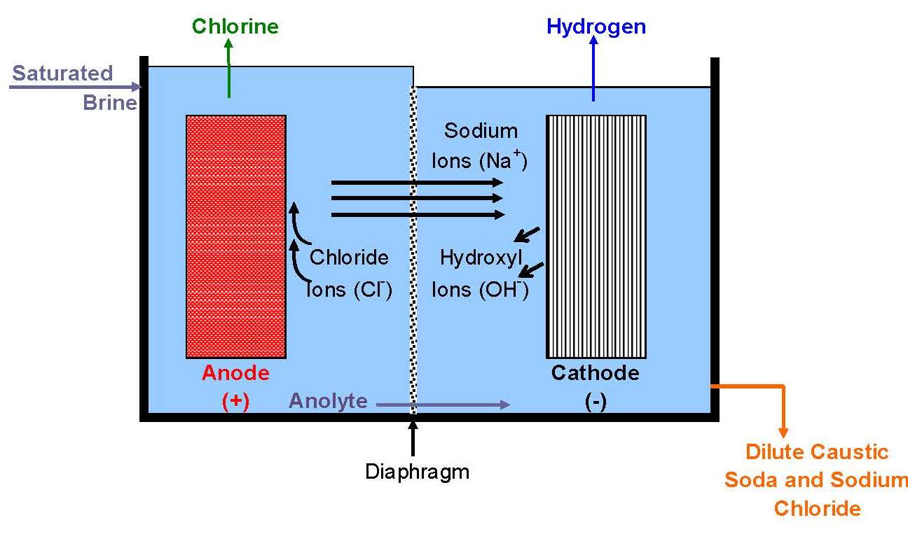
Electrochemical and chemical reactions occurring in diaphragm and membrane cells
| [1] | 2Cl- ==> Cl2 + 2e- | (anodic reaction) |
| [6] | 2H2O + 2e- ==> 2OH- + H2 | (cathodic reaction) |
| [6a] | O2 + 2H2O + 4e- ==> 4OH- | (oxygen depolarized cathodic reaction) |
| [7] | 2Cl- + 2H2O ==> Cl2 + H2 + 2OH- | (overall ionic reaction) |
| [5] | 2NaCl + 2H2O ==> Cl2 +2NaOH + H2 | (overall reaction) |
| [8] | Cl2 + 2NaOH ==> NaOCl + NaCl + H2O | (side reaction) |
| [9] | 3NaOCl ==> NaClO3 + 2NaCl | (side reaction) |
Reaction [9] will contaminate the caustic product with chlorate.
Chemical reactions occurring in brine processing
| [10] | CaSO4 + Na2CO3 ==> CaCO3 +NaSO4 | (CaCO3 precipitates) |
| [11] | MgCl2 + 2NaOH ==> Mg(OH)2 + 2NaCl | (Mg(OH)2 precipitates) |
Comparison of cell technologies
| Cell technology | Mercury | Diaphragm | Membrane |
| Operating current density ( kA/m2) | 8 - 13 | 0.9 - 2.6 | 3 - 6 |
| Cell voltage (V) | 3.9 - 4.2 | 2.9 - 3.5 | 2.9 - 3.4 |
| NaOH strength (wt%) | 50 | 12 | 32 |
| Energy consumption (AC kWh/MT Cl2) at a current density of (kA/m2) | 3400 (10) | 2800 (1.7) | 2600 (5) |
| Steam consumption for concentration to 50% NaOH; equivalent kWh/t Cl2) | 0 | 2.6; 900 | 0.7; 250 |
Process flow sheets
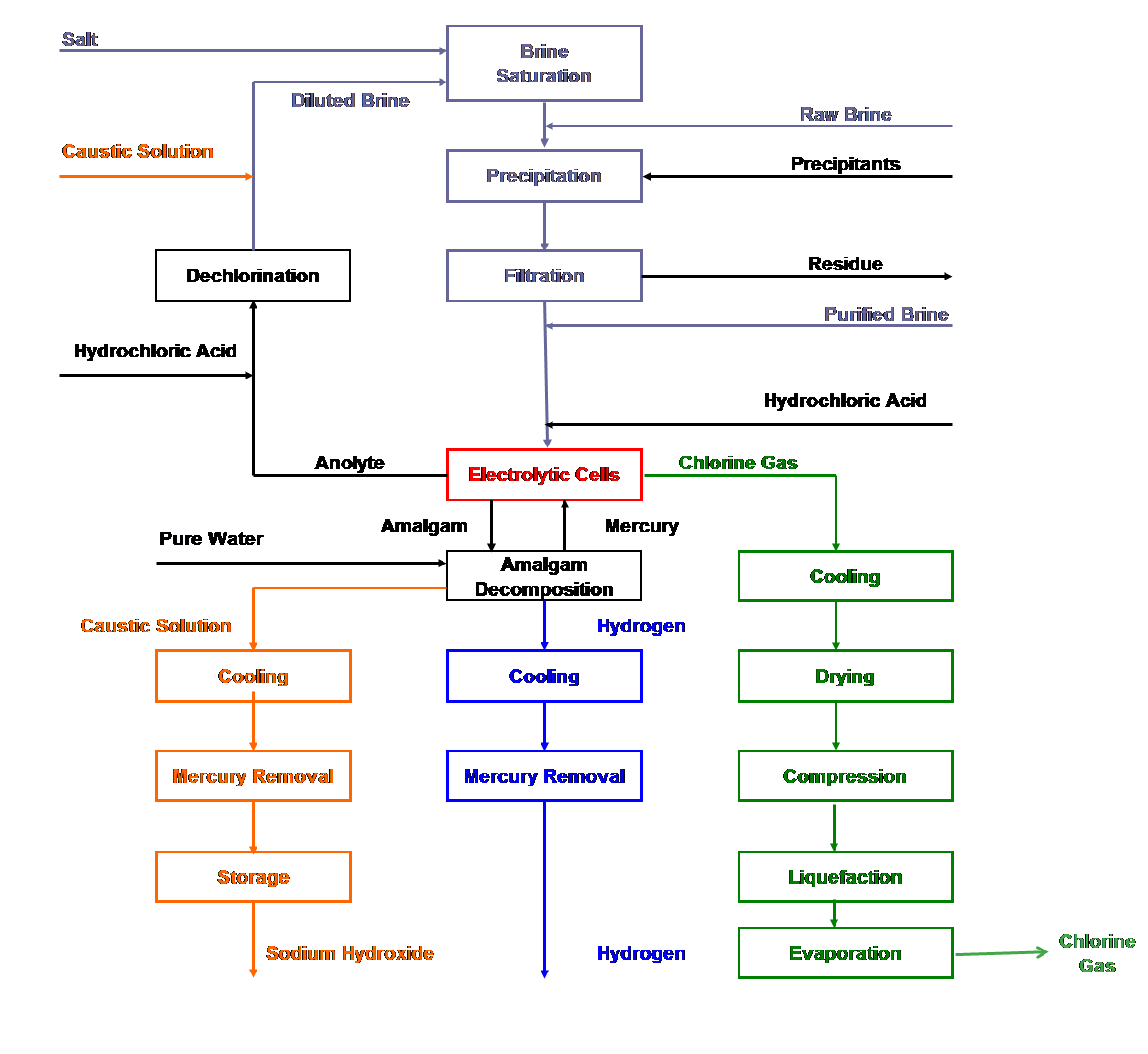 |
| Fig. 11. Mercury cell process flow sheet. |
![]()
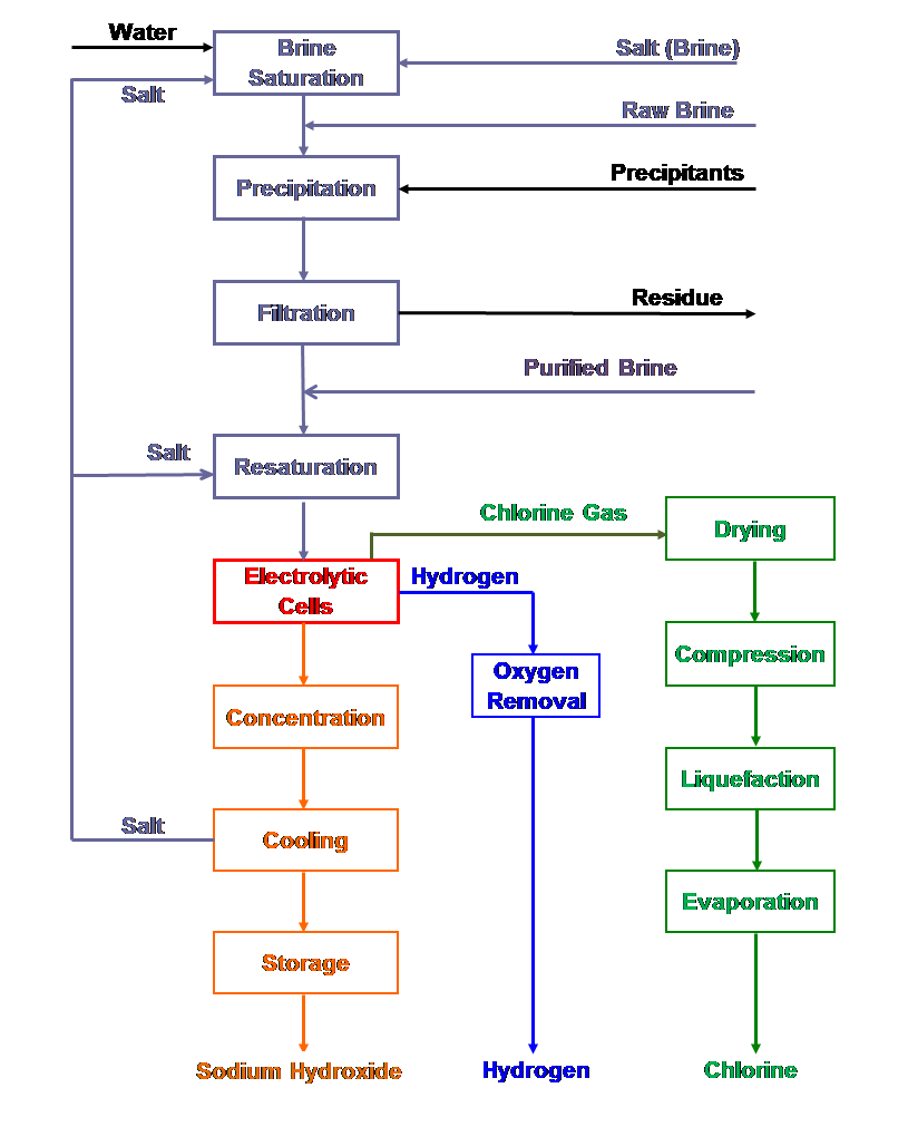 |
| Fig. 12. Diaphragm cell process flow sheet. |
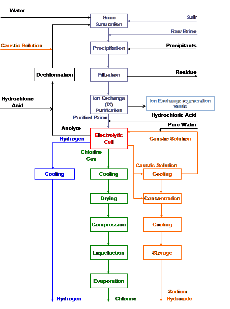 |
| Fig. 13. Membrane cell process flow sheet. |
![]() Sodium hypochlorite/chlorate manufacturing process
Sodium hypochlorite/chlorate manufacturing process
Electrochemical and chemical reactions occurring in cells
| [1] | 2Cl- ==> Cl2 + 2e- | (anodic reaction) |
| [7] | 2H2O + 2e- ==> 2OH- + H2 | (cathodic reaction) |
| [8] | Cl2 + 2OH- ==> OCl- + Cl- + H2O | (hypochlorite formation) |
| [9] | 3OCl- ==> ClO3- + 2Cl- | (chlorate formation) |
| [12] | NaCl + H2O ==> NaOCl + H2 | (overall hypochlorite reaction) |
| [13] | NaCl + 3H2O ==> NaClO3 + 3H2 | (overall chlorate reaction) |
| [14] | 3Cl2 + 6NaOH ==> NaClO3 + 5NaCl + 3H2O | (chemical chlorate formation) |
The use of weak brine, basic conditions, and low cell temperatures promote hypochlorite formation. The use of saturated brine, acidic solution, and temperatures close to the boiling point of the solution promote chlorate formation.
Chlorate cell process flow sheet
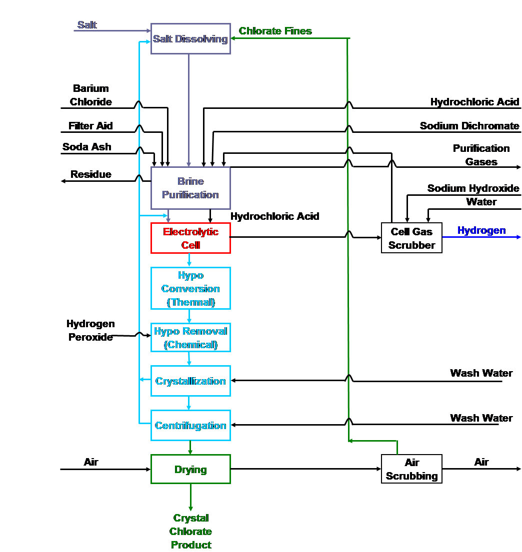 |
| Fig. 14. Chlorate cell process flow sheet. |
Acknowledgement
This article (in an earlier version) was, by permission, translated into Ukrainian and posted in the Gmail Archive at: http://www.stoodio.org/gmail-archive-art-b01-brine
Related articles
Aluminum production
Current density distribution in electrochemical cells
Extracting metals from sulfide ores
Industrial organics
Bibliography
- Process animations, Euro Chlor, Brussels, 2014.
- Salt, Chlor-Alkali, and Related Heavy Chemicals, T. F. O�Brien, in "Handbook of Industrial Chemistry and Biotechnology" (12th edition) Chapter 26, pp 1017-1038, J. A. Kent (editor), Springer, New York, 2013.
- Chlorine Industry Review 2012-2013, Euro Chlor, Brussels.
- ClorTec � On-Site Hypochlorite Generating Systems, brochure of Severn Trent Services, 2009.
- Chlor-Alkali Market Report, Chemical Market Associates, Inc., Issue No. 156-158, 2007.
- Chlorate capacity, AkzoNobel, 2009.
- Asbestos Ban Allows Chlor-Alkali Use, "Chemical and Engineering News" Vol. 85, No. 32, p 29, 2007.
- Handbook of Chlor-Alkali Technology, T. F. O'Brien, T. V. Bommaraju, and F. Hine, Springer, New York, NY 2005.
- Chlorine, in Kirk-Othmer Encyclopedia of Chemical Technology, T. V. Bommaraju et al., 5th edition, John Wiley and Sons, New York, 2002.
- Phase-Out Issues for Mercury Cell Technology in the Chlor-Alkali Industry,. M. Harris in "Modern Chlor-Alkali Technology", J. Moorhouse (editor), Vol. 8, pp 19-43, The Society of Chemical Industry, London, 2001.
- Chlorine: Principles and Industrial Practice, P. Schmittinger (editor), Wiley VCH, Weinheim. 2000.
- Decommisioning of Mercury Chlor-Alkali Plants, Environmental Protection 3, 2nd ed. Euro Chlor, Brussels, 1999.
- Federal Register, 63 (202), 56035, October 20, 1998.
- European Chemical News, p 22, March 31, 1997.
- Sodium Chlorate, J. E. Colman and B. V. Tilak, in "Encyclopedia of Chemical Processing and Design" J. J. McKetta and G. E. Weismantel (editors), Vol. 51, pp 126-188, Marcel Dekker, New York, 1995.
- Electrolytic Production of Sodium Chlorate, J. E. Colman, in "Tutorial Lectures in Electrochemical Engineering, American Institute of Chemical Engineers (AIChE) Symposium Series, No. 204," R. Alkire and T. Beck (editors), Vol. 77, pp 244-263, AIChE, New York, 1981.
- Chlorine: It's Manufacture, Properties and Uses, J. S. Sconce (editor), Reinhold, New York, 1962.
- The Chlorine Manual, Pamphlet #1, The Chlorine Institute, Arlington, VA.
Listings of electrochemistry books, review chapters, proceedings volumes, and full text of some historical publications are also available in the Electrochemistry Science and Technology Information Resource (ESTIR). (http://knowledge.electrochem.org/estir/)
Return to: Top – Encyclopedia Home Page – Table of Contents – Author Index – Subject Index – Search – Dictionary – ESTIR Home Page – ECS Home Page
ECS | Redcat Blog | ECS Digital Library