Return to:
Encyclopedia Home Page –
Table of Contents –
Author Index –
Subject Index –
Search –
Dictionary –
ESTIR Home Page –
ECS Home Page
FLOW BATTERIES
Robert F. Savinell
Department of Chemical Engineering, Case Western Reserve University
Cleveland, OH 44106, USA
(July, 2011)
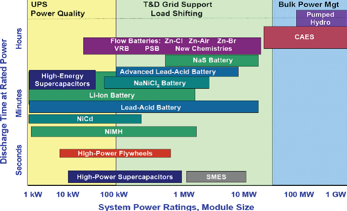 |
| Fig. 1. Power and energy densities of various energy-storage systems. |
Renewable energy sources, including wind and solar, can supply a significant amount of electrical energy in the United States and around the world. However, because of their intermittent nature, the potential of these two energy sources can be fully exploited only if efficient, safe, cost-effective, and reliable electrical energy-storage systems are provided. Storage systems will also be critical to improving the robustness and efficiency of the electrical distribution grid by reducing power surges and balancing the load over time. Energy-storage technologies suitable for applications involving various power capacities and storage time (energy capacity) are shown in Figure 1. For very large energy-storage applications, only pumped-hydro and compressed-gas are cost effective at this time. However, these technologies are limited by geography, while electrochemical energy-storage devices such as batteries, flow batteries, fuel cells, and electrochemical capacitors are promising because of their scalability and versatility. The size (weight and volume) of the device is not as critical for large scale energy storage as it is for portable and transportation applications. Capacitors have fast sub-second response times, deep discharge capability, and can deliver high power but for only short times, so these devices are more suitable for power quality management. Most fuel cells cannot be reversed electrically efficiently, as discussed below. Consequently, only batteries, both conventional and flow batteries, have the energy capacities needed for large-scale electrical energy storage.
Conventional and flow batteries
Flow batteries and fuel cells differ from conventional batteries in two main aspects. First, in a conventional battery, the electro-active materials are stored internally, and the electrodes, at which the energy conversion reactions occur, are themselves serve as the electrochemical oxidizing agent and fuel, for example the lead-oxide and lead electrodes in a lead-acid battery. In other words, the electrodes serve both as a structural component and as the electro-active materials. The characteristics of the negative and positive electrodes determine both power density (for example, electrical, transport and catalytic properties of the active material and non-reactive materials) and energy density (for example, mass of active materials) of the battery. As a battery converts its chemical energy to electrical energy, electrodes are consumed and undergo significant physical and chemical changes which affect its electrical performance. In contrast, in a flow battery the electro-active materials are stored externally and the electrodes serve only as structural components and passive source/sink of electrons. Second, because of the dual functions of its electrodes described above, a conventional battery has minimal or no scale-up advantages. Instead, it can only be scaled-out. That is, if more energy is needed, then more battery modules with identical components are required. As the amount of electro-active materials increases in a battery, more current collecting materials, electrolyte, separators, and enclosure materials are also needed. Consequently, a battery can never approach its theoretical energy density. Increasing the capacity of a battery almost always increases internal resistances and consequently decreases power density and efficiency. Furthermore, for multiple hour energy storage, a conventional battery will require oversizing the power capacity (thus increasing cost) since both energy and power are coupled to the battery capacity. In contrast, the capacity of a flow battery can be simply increased by increasing the size of the external storage tanks of the electro-active materials.
Flow battery classifications
A flow battery is an electrochemical device that converts the chemical energy of the electro-active materials directly to electrical energy, similar to a conventional battery and fuel cell. However, the electro-active materials in a flow battery are stored mostly externally and are introduced into the device only during operation. True flow batteries have all the reactants and products of the electro-active chemicals stored external to the power conversion device. Systems in which all the electro-active materials are dissolved in a liquid electrolyte are called redox (for reduction/oxidation) flow batteries. A schematic of a redox flow-battery system is shown in Figure 2 and a single cell construction is shown in Figure 3. Other true flow batteries might have a gas species (for example, hydrogen, oxygen, chlorine) and/or liquid species (for example, bromine). Reversible fuel cells like hydrogen/chlorine and hydrogen/bromine, or even high temperature reversible hydrogen/oxygen solid oxide fuel cells could be thought of as flow batteries. Systems in which one or more electro-active components are stored internally are hybrid flow batteries. Examples include the zinc-bromine and the zinc-chlorine batteries in which zinc is included in the electrode design but chlorine or bromine can be fed from an external tank. As with conventional batteries, the energy capacity of these hybrid flow batteries is limited by the amount of electro-active materials that can be stored within the electrodes of the battery and they have limited scale-up advantages.
 |
| Fig. 2. Schematic of a redox flow-battery system shown in a discharge mode. |
|
| Fig. 3. An exploded view of a single redox flow-battery cell. |
|
| Fig. 4. Schematics representing the electrochemical reactions in the iron/chrome redox battery. |
Most redox flow batteries consist of two separate electrolytes, one storing the electro-active materials for the negative electrode reactions and the other for the positive electrode reactions. (To prevent confusion, the negative electrode is the anode and the positive electrode is the cathode during discharge. It is to be noted that these names will be reversed during charge, while the polarity of the electrodes, negative/positive, remains unchanged.) Both the fresh and spent electrolytes may be circulated and stored in a single storage tank as shown in Figure 2. An ion selective membrane is often used to prevent mixing or cross-over of the electro-active species which results in chemical short-circuit of electro-active materials. Only the common counter-ion carrier is allowed to cross the membrane. Figure 4 shows a simplified drawing of the electrochemical charging reactions one of the most commonly suggested redox battery for utility scale application, the iron/chrome system. During power generation (discharge of the battery) the chromium ion oxidizes the iron ion in the solution. In this system the separator allows passage of a chloride anion to balance the charge. Details of these reactions, together with the description of a number of other possible flow-battery systems are shown in the Appendix.
A fuel cell might be considered as a type of flow battery in that the power conversion component is independent of the chemical energy capacity of the device. Most fuel cells involve oxygen at the positive electrode, and cannot be reversed electrically efficiently, and consequently cannot be used effectively as an electrical energy-storage device. The exception might be a high temperature solid oxide fuel cell.
Advantages and disadvantages
With the electrolyte and electro-active materials stored externally, true flow batteries have many advantages, one of which is the separation of the power and energy requirements. The electrodes, not being part of the electro-active materials, can be designed to have optimal power acceptance and delivery properties (for example, electrical, transport, and catalytic) without the need to also maximize energy-storage density. Furthermore, the electrodes do not undergo physical and chemical changes during operation (because they do not contain active materials), thus leading to more stable and durable performance. Therefore, engineered microstructures developed to optimize performance can be maintained over the lifetime of the device. With longer life times, the capital cost of the battery system can be amortized over a longer period, thus reducing the cost of the energy-storage device. A wider state of charge operating window possible with the redox batteries reduces the quantity of electro-active material required to deliver power over the entire required duration of discharge, also reducing cost further.
The energy-capacity requirement of a flow battery is determined by the size of the external storage components. Consequently, a redox flow-battery system could approach its theoretical energy density as the system is scaled up to a point where the weight or volume of the battery is small relative to that of the stored fuel and oxidant. An analogous, but conventional system is the internal combustion engine system, in which the power is determined by the size of the engine and the energy capacity is determined by the size of the fuel tank.
A flow battery has a safety advantage that comes from storing the active materials separately from the reactive point source. Other advantages are quick response times (common to all battery systems), high electricity-to-electricity conversion efficiency, no cell-to-cell equalization requirement, simple state-of-charge indication (based on electro-active concentrations), low maintenance, tolerance to overcharge and over-discharge, and perhaps most importantly, the tolerance for deep discharges without affecting cycle life. The hybrid systems like those involving zinc plating do not offer all these advantages, but still have many of the desirable features of a true flow battery. The main disadvantage of flow batteries is their more complicated system requirements of pumps, sensors, flow and power management, and secondary containment vessels, making them most suitable for large-scale storage applications.
The cost of an energy-storage device is a major impediment to utility adoption. For example, in the vanadium flow-battery system, one of the few redox flow batteries that have been tested at the utility scale, vanadium itself is a significant cost contributor. Analysis suggests that the cost of vanadium chemicals varies widely, but could contribute between $50/kWh to $110/kWh, or from 50-100% of the cost target of $100-$200/kWh for the energy-storage system. From this standpoint, identifying low cost redox couples with high solubility is critical to meeting market requirements.
The other key cost factor is the construction of the electrochemical cell itself. The construction cost of the cell scales with the total power requirement of the application, but these costs are directly related to the specific power of the device itself - how effectively the rates of the materials are utilized. While flow batteries ought to be able to operate at relatively high current densities, as convection can be employed to deliver reactants to the electrode surface, flow batteries have typically been operated at ~50 mA/cm2, a current density consistent with conventional batteries without convection. It is anticipated that electrolyte management and cell design can deliver at least 5- to 10-fold improvement in power density, thereby reducing the stack cost.
Future directions
Only a few flow-battery systems have seen deployment. Consequently, the technologies are relatively new and unfamiliar. Overall, the primary barriers to commercialization for large scale energy storage are round trip energy-storage efficiency, cost for energy storage in terms of $/kWh, and cost for the power capacity in terms of $/kW. Further development will require research and development activities in the following areas.
- Low-cost, efficient, and durable electrodes; current electrodes are graphite or carbon fiber felt materials. Enhancing electrocatalytic properties of the fiber surfaces for faster and more reversible reactions and optimizing structure for transport and current distribution will improve cell and stack efficiency and increase power density.
- Chemically stable redox couples, having large potential differences, with high solubilities of both oxidized and reduced species, and fast redox kinetics; approaches with non-aqueous electrolytes offer for the possibility of higher cell voltage couples for greater energy and power density.
- Highly permselective and durable membranes; in many redox batteries the membrane is based on costly perfluorinated polymer material. Lower cost non-perfluorinated materials might be appropriate for redox battery applications because of the milder operating conditions as compared to fuel cells. In some applications, even lower cost micro-porous separator materials might work as well. Besides low cost, high performance will require high conductivity and selectivity of desired ion transport to minimize reactant crossover.
- Electrode structure and cell design that minimize transport losses, improve efficiency, and reduce cost; advances in fuel cell designs during the past two decades may find applications here to uniformly distribute electrolyte within the cell. Also, advances in bi-polar plate material, spacer/sealing material, and stack fabrication cost reduction of recent fuel cell advances will be useful here.
- Designs with minimal pumping and shunt current losses; because of liquid electrolytes, these types of losses become even more significant for stacks with large numbers of cells.
- Large scale power and system management and grid integration. Understanding impedance matches, transient response times, ac-dc-ac conversion, etc. are required to deploy electrical energy storage technologies into utility applications.
Appendix

|
| Fig. 5. Schematics representing the electrochemical reactions in the all vanadium redox battery. |
Table I shows some of the more well-known flow-battery systems.
Both the fresh and spent electrolytes may be circulated and stored in a single storage tank as shown in Figure 2, or in separate tanks to control the concentrations of the electro-active material. An ion selective membrane is often used to prevent mixing or cross-over of the electro-active species which results in chemical short-circuit of electro-active materials. Only the common counter ion carrier is allowed to cross the membrane. For example, in the bromine-polysulfide system, as Na2S2 is converted to Na2S4 at the negative electrode and Br2 is converted to 2Br- at the positive electrode, the excess Na+ ions at the negative electrode are allowed to cross to the positive electrode to maintain electroneutrality. Figure 4 and 5 show a simplified drawing of the electrochemical reactions for two common redox flow-battery couples; the iron/chrome system and the all vanadium system. In the iron/chrome system the separator allows passage of an anion to balance the charge. This system was one of the earlier flow-battery chemistries studied for utility scale application. In the vanadium system, as V+2 is oxidized to V+3 at the negative electrode and V+5 is reduced to V+4 at the positive electrode, hydronium ions are transported across a proton conducting membrane from the negative electrode to the positive electrode. In this case, however sometimes a microporous non-selective membrane separator can be used since most of the current might be carried by high mobility protons in the acid electrolyte and since the cross-over of the common vanadium cation lowers efficiency but does not cause a permanent loss of capacity.
| Table I. Characteristics of some flow-battery systems |
| System | Reactions
top: negative; bottom: positive electrode
charge: <== ; discharge: ==> |
Eocell |
Electrolyte
-/+ electrode |
| Redox |
| All vanadium |
V2+ <==> V3+ + e-
VO2+ + e- <==> VO2+ |
1.4 V |
H2SO4/H2SO4 |
| Vanadium-polyhalide |
V2+ <==> V3+ + e-
�Br2 + e- <==> Br- |
1.3 V |
VCl3-HCl/NaBr-HCl |
| Bromine-polysulfide |
2S22- <==> S42- + 2e-
Br2 + 2e- <==> 2Br- |
1.5 V |
NaS2/NaBr |
| Iron-chromium |
Fe2+ <==> Fe3+ + e-
Cr3+ + e- <==> Cr2+ |
1.2 V |
HCl-FeCl2-CrCl3
(both sides) |
| Hydrogen-bromine |
H2 <==> 2H+ + 2e-
Br2 + 2e- <==> 2Br- |
1.1 V |
HBr-PEM* |
| Hybrid |
| Zinc-bromine |
Zn <==> Zn2+ + 2e-
Br2 + 2e- <==> 2Br- |
1.8 V |
ZnBr2/ZnBr2 |
| Zinc-cerium |
Zn <==> Zn2+ + 2e-
2Ce4+ + 2e- <==> 2Ce3+ |
2.4 V |
CH3SO3H
(both sides) |
| * Proton exchange membrane |
Related articles
Fuel cells
Nonrechargeable batteries
Solid-oxide fuel cells
Bibliography
- Progress in Flow Battery Research and Development, M. Skyllas-Kazacos, M. H. Chakrabarti, S. A. Hajimolana, F. S. Mjalli, and M. Saleem, �Journal of the Electrochemical Society� Vol. 158, pp R55-R79, 2011.
- Energy Storage for the Electricity Grid: Benefits and Market Potential Assessment Guide, J. Eyer and G. Corey, �Report of the Sandia National Laboratory� SAND2010-0815, February, 2010.
- Redox Flow Cells for Energy Conversion, C. Ponce de Leon, A. Frias-Ferrer, J. Gonzalez-Garcia, D. A. Szanto, and F. C. Walsh, �Journal of Power Sources� Vol. 160, pp 716-732, 2006.
- Secondary Batteries-Introduction, J. McBreen, in �Comprehensive Treatise of Electrochemistry� Vol. 3, pp 303-340, J. O�M. Bockris, B. E. Conway, E. Yeager, and R. E. White (editors), Plenum Press, New York, 1981.
Listings of electrochemistry books, review chapters, proceedings volumes, and full text of some historical publications are also available in the Electrochemistry Science and Technology Information Resource (ESTIR). (http://knowledge.electrochem.org/estir/)
Return to:
Top –
Encyclopedia Home Page –
Table of Contents –
Author Index –
Subject Index –
Search –
Dictionary –
ESTIR Home Page –
ECS Home Page
|